Toyota Tacoma (2015-2018) Service Manual: Components
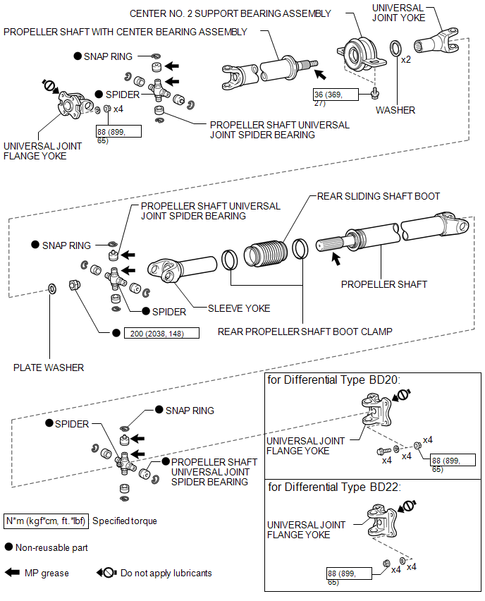
COMPONENTS
ILLUSTRATION

 Removal
REMOVAL
PROCEDURE
1. REMOVE PROPELLER SHAFT WITH CENTER BEARING ASSEMBLY
(a) Place matchmarks on the propeller shaft flange yoke and differential
flange.
Text in Illustration
...
Other materials:
Pressure Sensor Circuit (B1423/23)
DESCRIPTION
This DTC is stored if refrigerant pressure on the high pressure side is extremely
low (176 kPa (1.8 kgf/cm2, 26 psi) or less) or extremely high (3140 kPa (32.0 kgf/cm2,
455 psi) or more). The air conditioner pressure sensor, which is installed on the
pipe on the high pressure side ...
Trailer Socket
Components
COMPONENTS
ILLUSTRATION
Removal
REMOVAL
PROCEDURE
1. REMOVE TRAILER SOCKET
(a) Disconnect the connector.
(b) Disengage the 2 clips to remove the trailer socket.
Install ...
Power Outlet Socket(for Rear Side)
Components
COMPONENTS
ILLUSTRATION
*1
USB CHARGER SOCKET
-
-
Removal
REMOVAL
PROCEDURE
1. REMOVE REAR CONSOLE BOX ASSEMBLY
Click here
2. REMOVE USB CHARGER SOCKET
(a) Disengage the 4 claws to remove the USB charger soc ...
