Toyota Tacoma (2015-2018) Service Manual: Reassembly
REASSEMBLY
PROCEDURE
1. INSTALL UPPER RADIATOR TANK
|
(a) Install a new upper radiator tank. Text in Illustration
|
|
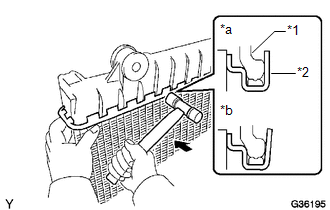
(b) Tap the core plate with a plastic hammer until there is no gap between the core plate and upper radiator tank.
2. INSTALL LOWER RADIATOR TANK
HINT:
Perform the same procedures as for the upper radiator tank.
3. ASSEMBLE SST
|
(a) Install the punch assembly into the overhaul handle by inserting it into the hole in part A as shown in the illustration. Text in Illustration
SST: 09230-01010 09231-01010 09231-01020 |
|
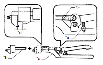
(b) While gripping the handle, adjust the stopper bolt so that dimension B is as shown in the illustration.
Dimension B:
8.4 mm (0.331 in.)
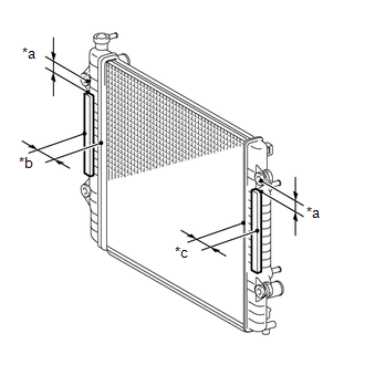
4. CAULK CORE PLATE
|
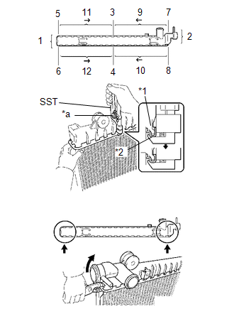
(a) Gently press SST against the core plate in the order shown in the illustration. After repeating this a few times, fully caulk the core plate by gripping the handle until stopped by the stopper bolt. Text in Illustration
SST: 09230-01010 09231-01010 09231-01020 NOTICE:
|
|
|
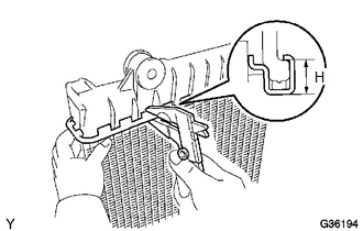
(b) Check the core plate height (H) after completing the caulking. Plate height (H): 8.7 to 9.1 mm (0.343 to 0.358 in.) If the height is not as specified, readjust the stopper bolt of the handle, then caulk it again. |
|
5. INSTALL RADIATOR SUPPORT BUSHING
|
(a) Install the 2 No. 1 radiator support collars and 2 No. 1 radiator support bushings to the radiator assembly. Text in Illustration
NOTICE: With the hook of the No. 1 radiator support collar facing towards the top of the vehicle, install the No. 1 radiator support collar. |
|
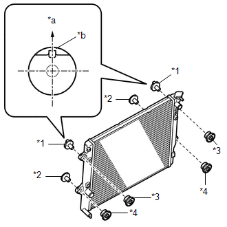
(b) Install the 2 No. 2 radiator support collars and 2 No. 2 radiator support bushings to the radiator assembly.
6. INSTALL RADIATOR TO SUPPORT SEAL
|
(a) Install 2 new radiator to support seals to the radiator assembly as shown in the illustration. Text in Illustration
|
|
7. INSTALL RADIATOR DRAIN COCK PLUG
(a) Install a new O-ring to the radiator drain cock plug.
(b) Install the radiator drain cock plug to the radiator assembly.
 Installation
INSTALLATION
PROCEDURE
1. INSTALL RADIATOR ASSEMBLY
(a) Engage the 2 hooks and temporarily install the radiator assembly to the radiator
support sub-assembly.
(b) Install the radiator assembly w ...
 Thermostat
...
Other materials:
Components
COMPONENTS
ILLUSTRATION
ILLUSTRATION
ILLUSTRATION
*1
COMPRESSOR PICK UP SENSOR
*2
MAGNET CLUTCH ASSEMBLY
*3
PRESSURE RELIEF VALVE
*4
COMPRESSOR SPACER
*5
O-RING
...
Neutral Position Switch
Components
COMPONENTS
ILLUSTRATION
*1
NEUTRAL POSITION SWITCH
*2
GASKET
N*m (kgf*cm, ft.*lbf): Specified torque
â—Ź
Non-reusable part
Installation
INSTALLATION
PROCEDURE
1. INSTALL NEUTR ...
Installation
INSTALLATION
PROCEDURE
1. INSTALL FRONT DISC
(a) Align the matchmarks of the front disc and the front axle hub and
install the front disc.
Text in Illustration
*a
Matchmark
HINT:
When replacing the disc with a new one, se ...
