Toyota Tacoma (2015-2018) Service Manual: Components
COMPONENTS
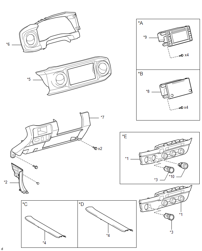
ILLUSTRATION
|
*A |
w/o Navigation System |
*B |
w/ Navigation System |
|
*C |
for Double Cab |
*D |
for Acces Cab |
|
*E |
for 4WD |
- |
- |
|
*1 |
AIR CONDITIONING CONTROL ASSEMBLY |
*2 |
COWL SIDE TRIM BOARD LH |
|
*3 |
ENGINE SWITCH |
*4 |
FRONT DOOR SCUFF PLATE LH |
|
*5 |
INSTRUMENT CLUSTER CENTER FINISH PANEL SUB-ASSEMBLY |
*6 |
INSTRUMENT CLUSTER FINISH PANEL ASSEMBLY |
|
*7 |
INSTRUMENT PANEL LOWER FINISH PANEL SUB-ASSEMBLY |
*8 |
NAVIGATION RECEIVER ASSEMBLY WITH BRACKET |
|
*9 |
RADIO AND DISPLAY RECEIVER ASSEMBLY WITH BRACKET |
*10 |
TRANSFER POSITION SWITCH |

 Installation
INSTALLATION
PROCEDURE
1. INSTALL TRANSFER POSITION SWITCH (for 4WD)
Click here
2. INSTALL ENGINE SWITCH
Click here
3. INSTALL AIR CONDITIONING CONTROL ASSEMBLY
(a) Connect the connectors.
...
Other materials:
Engine Switch Illumination Circuit
DESCRIPTION
The illuminated entry system controls the engine switch illumination.
WIRING DIAGRAM
PROCEDURE
1.
READ VALUE USING TECHSTREAM (POWER/ENGINE SW LIGHT)
(a) Connect the Techstream to the DLC3.
(b) Turn the engine switch to ON.
(c) Turn the Techstream ...
Position Initialization Incomplete (B2343)
DESCRIPTION
This DTC is stored when the sliding roof ECU (sliding roof drive gear sub-assembly)
has not been initialized.
DTC No.
DTC Detection Condition
Trouble Area
B2343
Sliding roof ECU (sliding roof drive gear sub-assembly) has no ...
High Pitched Horn
Components
COMPONENTS
ILLUSTRATION
Removal
REMOVAL
PROCEDURE
1. REMOVE RADIATOR GRILLE
Click here
2. REMOVE HIGH PITCHED HORN ASSEMBLY
(a) Disconnect the connector.
(b) Remove the bolt and high pitched horn assembly.
Inspection
...
