Toyota Tacoma (2015-2018) Service Manual: Reassembly
REASSEMBLY
PROCEDURE
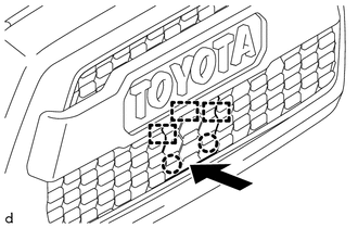
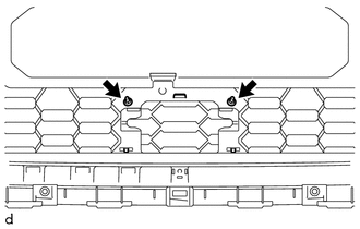
1. INSTALL RADIATOR GRILLE MOULDING
|
(a) Engage the 8 claws to install the radiator grille moulding. |
|
.png)
(b) Install the 8 screws.
2. INSTALL NO. 1 RADIATOR GRILLE GARNISH
(a) for Type A and Type B:
|
(1) Engage the 2 guides and 4 claws and 2 pins as shown in the illustration. |
|
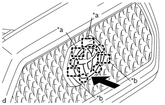
|
(2) Install the No. 1 radiator grille garnish with 2 new spring nuts. |
|
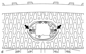
(b) for Type C:
|
(1) Engage the 3 guides and 2 claws as shown in the illustration. |
|
|
(2) Install the No. 1 radiator grille garnish with 2 new spring nuts. |
|
3. INSTALL MILLIMETER WAVE RADAR SENSOR ASSEMBLY (w/ Toyota Safety Sense P)
Click here .gif)
4. INSTALL MILLIMETER WAVE RADAR WIRE (w/ Toyota Safety Sense P)
Click here
 Installation
INSTALLATION
PROCEDURE
1. INSTALL RADIATOR GRILLE
(a) Engage the 10 guides to install the radiator grille.
(b) Install the 2 clips.
(c) Install the 2 screws.
(d) Remove the protective tape.
(e) ...
 Rear Body Side Panel Protector
Components
COMPONENTS
ILLUSTRATION
ILLUSTRATION
Installation
INSTALLATION
CAUTION / NOTICE / HINT
HINT:
Use the same procedure for the RH side and LH side.
The following pr ...
Other materials:
Installation
INSTALLATION
PROCEDURE
1. INSTALL FUEL SUCTION TUBE SET GASKET
(a) Ensure gasket groove is clean and free of foreign particles.
(b) Install a new gasket onto the fuel tank.
(c) Make sure that the gasket sits in the groove.
2. INSTALL FUEL SU ...
On-vehicle Inspection
ON-VEHICLE INSPECTION
PROCEDURE
1. INSPECT REFRIGERANT PRESSURE WITH MANIFOLD GAUGE SET
(a) This is a method to specify trouble areas by using a manifold gauge set.
Read the manifold gauge pressure when the following conditions are established.
Test conditions:
Engine has been warmed u ...
Sleep Operation Failure of Occupant Classification ECU (B1796)
DESCRIPTION
During sleep mode, the occupant detection ECU monitors the condition of each
sensor while the ignition switch is off. In this mode, if the occupant detection
ECU detects an internal malfunction, DTC B1796 is set.
DTC No.
DTC Detections Conditions
Tr ...
