Toyota Tacoma (2015-2018) Service Manual: Ignition Coil And Spark Plug
Components
COMPONENTS
ILLUSTRATION
Installation
INSTALLATION
PROCEDURE
1. INSTALL SPARK PLUG
HINT:
Perform "Inspection After Repairs" after replacing the spark plug (See page
.gif) ).
).
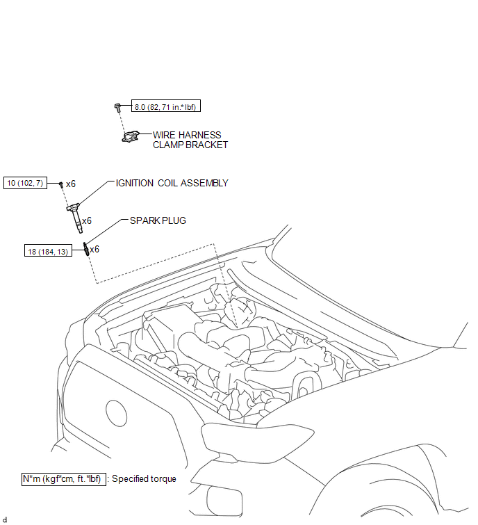
(a) Install the 6 spark plugs.
Torque:
18 N·m {184 kgf·cm, 13 ft·lbf}
2. INSTALL IGNITION COIL ASSEMBLY
HINT:
Perform "Inspection After Repairs" after replacing the ignition coil assembly
(See page ).
(a) Install the 6 ignition coils with the 6 bolts.
Torque:
10 N·m {102 kgf·cm, 7 ft·lbf}
(b) Connect the 6 connectors to the 6 ignition coil assemblies.
3. INSTALL WIRE HARNESS CLAMP BRACKET
(a) Install the wire harness clamp bracket with the bolt.
Torque:
8.0 N·m {82 kgf·cm, 71 in·lbf}
(b) Engage the 2 clamps and connect the wire harness to the wire harness clamp bracket.
4. INSTALL INTAKE AIR SURGE TANK ASSEMBLY
(See page )
Removal
REMOVAL
PROCEDURE
1. REMOVE INTAKE AIR SURGE TANK ASSEMBLY
(See page .gif) )
)
2. REMOVE WIRE HARNESS CLAMP BRACKET
|
(a) Disengage the 2 clamps to disconnect the wire harness from the wire harness clamp bracket. |
|
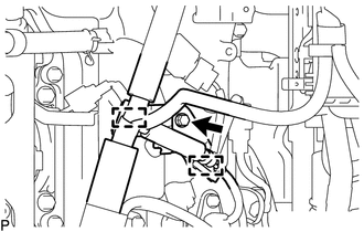
(b) Remove the bolt and wire harness clamp bracket.
3. REMOVE IGNITION COIL ASSEMBLY
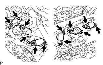
(a) Disconnect the 6 connectors from the 6 ignition coil assemblies.
(b) Remove the 6 bolts and 6 ignition coil assemblies.
4. REMOVE SPARK PLUG
(a) Remove the 6 spark plugs.
 2gr-fks Ignition
...
 Ignition System
...
Other materials:
Parking Brake Lever
Components
COMPONENTS
ILLUSTRATION
ILLUSTRATION
Installation
INSTALLATION
PROCEDURE
1. INSTALL PARKING BRAKE SWITCH ASSEMBLY
2. INSTALL PARKING BRAKE LEVER SUB-ASSEMBLY
(a) Install the 2 toothed washers and parking brake lever support to the parking
brake lever.
(b) Install th ...
Data List / Active Test
DATA LIST / ACTIVE TEST
1. DATA LIST
HINT:
Using the Techstream to read the Data List allows the values or states of switches,
sensors, actuators and other items to be read without removing any parts. This non-intrusive
inspection can be very useful because intermittent conditions or signals ...
How To Proceed With Troubleshooting
CAUTION / NOTICE / HINT
HINT:
Use the following procedure to troubleshoot the sliding roof system.
*: Use the Techstream.
PROCEDURE
1.
VEHICLE BROUGHT TO WORKSHOP
NEXT
...
