Toyota Tacoma (2015-2018) Service Manual: Rear Door(for Double Cab)
Components
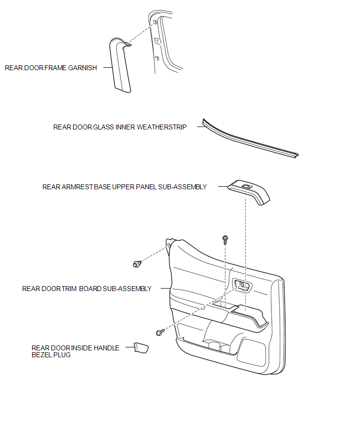
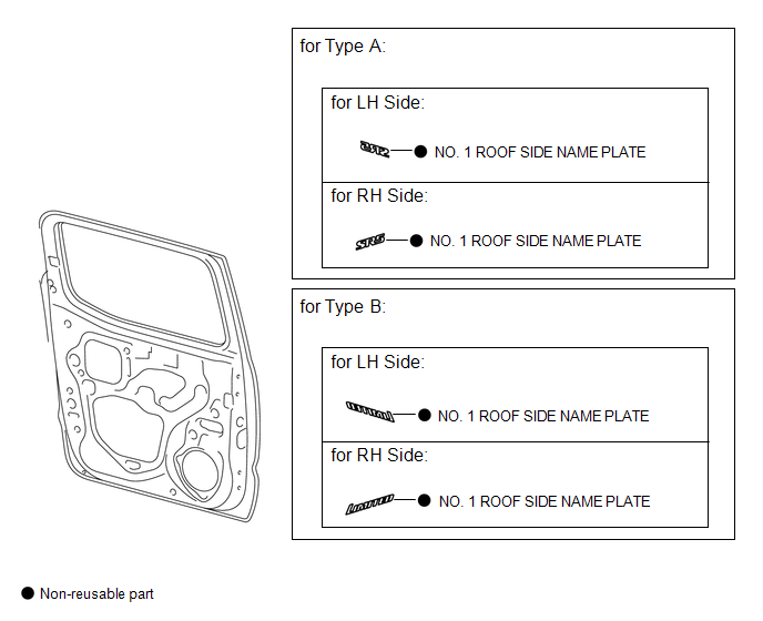
COMPONENTS
ILLUSTRATION
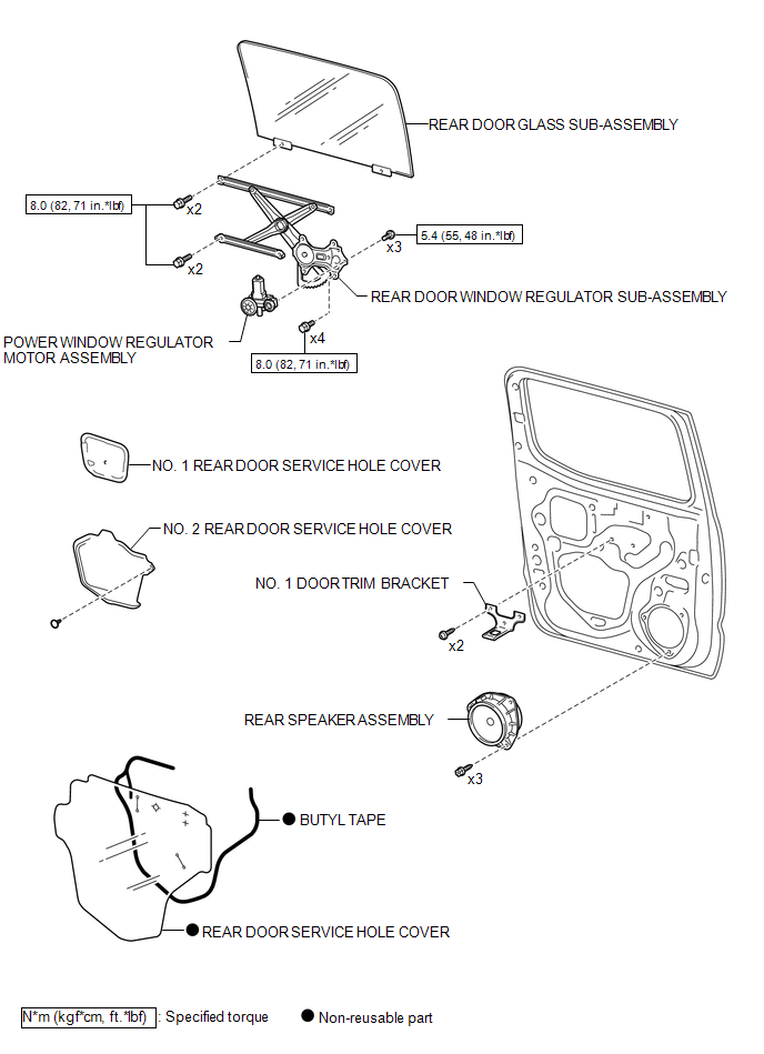
ILLUSTRATION
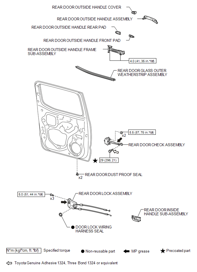
ILLUSTRATION
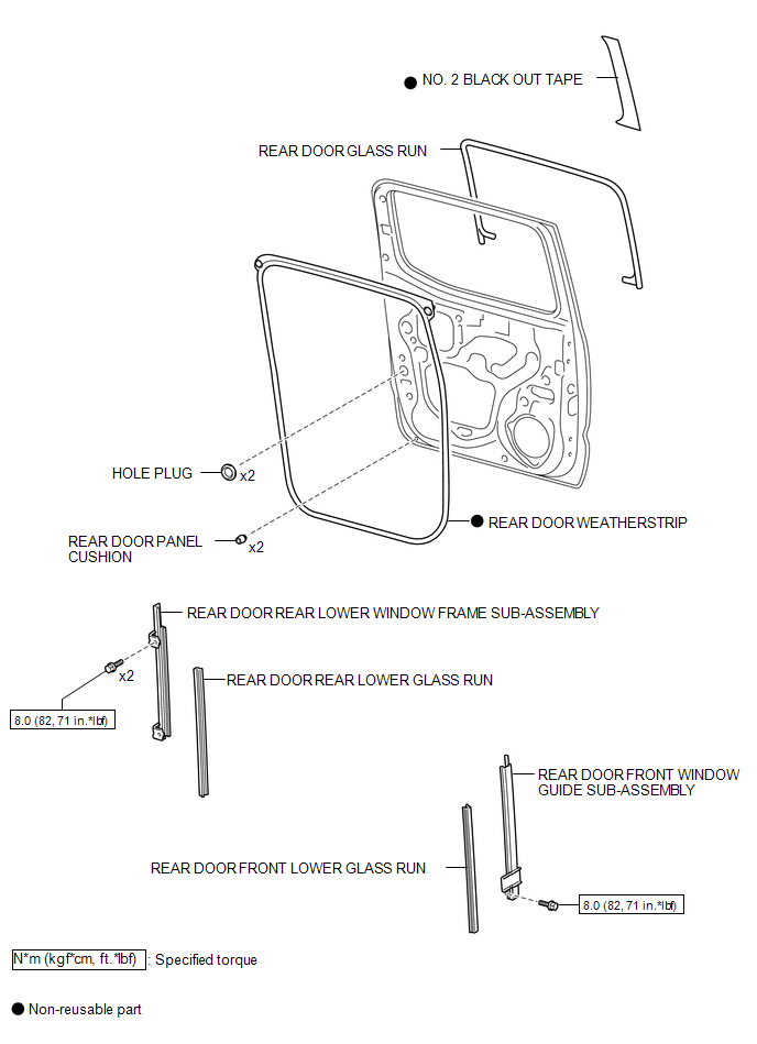
ILLUSTRATION
ILLUSTRATION
Adjustment
ADJUSTMENT
CAUTION / NOTICE / HINT
HINT:
- Use the same procedures for both the LH and RH sides.
- The procedure described below is for the LH side.
- Centering bolts are used to mount the door hinge to the vehicle body
and door. The door cannot be adjusted with the centering bolts on. Substitute
the centering bolts for standard bolts when making adjustments.
.png) Text in Illustration
Text in Illustration
*1
Centering Bolt
*2
Standard Bolt
- A bolt without a torque specification is shown in the standard bolt
chart (See page
.gif) ).
).
PROCEDURE
1. INSPECT REAR DOOR PANEL SUB-ASSEMBLY
(a) Check that the clearance measurements of areas "A" through "F" are within each standard range.
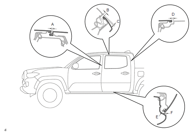 Standard Clearance:
|
Area |
Measurement |
Area |
Measurement |
|---|---|---|---|
|
A |
3.5 to 6.5 mm (0.138 to 0.256 in.) |
B |
3.3 to 6.3 mm (0.130 to 0.248 in.) |
|
C |
0.2 to 3.2 mm (0.008 to 0.126 in.) |
D |
2.9 to 5.9 mm (0.114 to 0.232 in.) |
|
E |
3.4 to 6.4 mm (0.134 to 0.252 in.) |
F |
0.5 to 3.5 mm (0.020 to 0.138 in.) |
2. ADJUST REAR DOOR PANEL SUB-ASSEMBLY
|
(a) Adjust the door horizontally and vertical by loosening the 4 body side hinge bolts. |
|
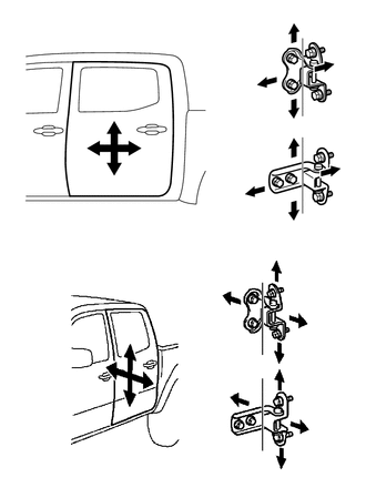
(b) Tighten the 4 body side hinge bolts after the adjustment.
Torque:
26 N·m {265 kgf·cm, 19 ft·lbf}
NOTICE:
Adjust the door fitting after the bolts were replaced with new ones.
(c) Adjust the door horizontally and vertical by loosening the 4 door side hinge bolts.
(d) Tighten the 4 door side hinge bolts after the adjustment.
Torque:
26 N·m {265 kgf·cm, 19 ft·lbf}
NOTICE:
Adjust the door fitting after the bolts were replaced with new ones.
|
(e) Using a T40 "TORX" socket wrench, slightly loosen the 2 striker mounting screws. |
|
.png)
(f) Using a brass bar and a hammer, hit the striker to adjust its position.
(g) Using a T40 "TORX" socket wrench, tighten the 2 striker mounting screws after adjustment.
Torque:
23 N·m {235 kgf·cm, 17 ft·lbf}
 Rear Door(for Access Cab)
Adjustment
ADJUSTMENT
CAUTION / NOTICE / HINT
HINT:
Use the same procedures for both the LH and RH sides.
The procedure described below is for the LH side.
Centering bolts are us ...
 Tail Gate
...
Other materials:
Removal
REMOVAL
CAUTION / NOTICE / HINT
NOTICE:
If one of the camshaft timing gear bolts is already removed, do not remove any
other camshaft timing gear bolts.
PROCEDURE
1. REMOVE NO. 2 ENGINE UNDER COVER SUB-ASSEMBLY (w/ Off Road Package)
2. REMOVE NO. 1 ENGINE UNDER COVER SUB-ASSEMBLY
3. REMOVE ...
Components
COMPONENTS
ILLUSTRATION
ILLUSTRATION
ILLUSTRATION
ILLUSTRATION
ILLUSTRATION
*A
w/ Seat Heater System
-
-
*1
FRONT SEAT CUSHION HEATER ASSEMBLY
*2
FRONT SEATBACK HEATER ASSEMBLY
...
USB Audio System Recognition/Play Error
DESCRIPTION
When a USB device or "iPod" is connected to the USB jack of the No. 1 stereo
jack adapter assembly, it must have playable files. The device must also communicate
with and be recognized by the radio and display receiver assembly. This diagnosis
procedure is for when a dev ...
