Toyota Tacoma (2015-2018) Service Manual: Clearance Warning ECU Power Source Circuit
DESCRIPTION
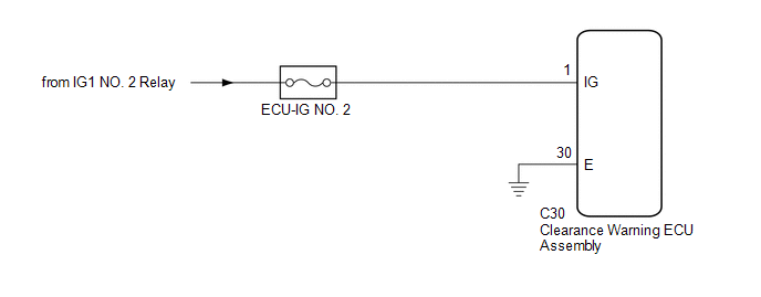
This circuit provides power to operate the clearance warning ECU assembly.
WIRING DIAGRAM
CAUTION / NOTICE / HINT
NOTICE:
Inspect the fuse for circuits related to this system before performing the following inspection procedure.
PROCEDURE
|
1. |
CHECK HARNESS AND CONNECTOR (CLEARANCE WARNING ECU ASSEMBLY POWER SOURCE) |
(a) Disconnect the C30 connector from the clearance warning ECU assembly.
(b) Measure the voltage according to the value(s) in the table below.
Standard Voltage:
|
Tester Connection |
Condition |
Specified Condition |
|---|---|---|
|
C30-1 (IG) - Body ground |
Ignition switch ON |
11 to 14 V |
|
C30-1 (IG) - Body ground |
Ignition switch off |
Below 1 V |
| NG | .gif) |
REPAIR OR REPLACE HARNESS OR CONNECTOR |
|
.gif)
|
2. |
CHECK HARNESS AND CONNECTOR (CLEARANCE WARNING ECU ASSEMBLY - BODY GROUND) |
(a) Measure the resistance according to the value(s) in the table below.
Standard Resistance:
|
Tester Connection |
Condition |
Specified Condition |
|---|---|---|
|
C30-30 (E) - Body ground |
Always |
Below 1 Ω |
| OK | |
PROCEED TO NEXT SUSPECTED AREA SHOWN IN PROBLEM SYMPTOMS TABLE |
| NG | |
REPAIR OR REPLACE HARNESS OR CONNECTOR |
 Clearance Warning Buzzer Circuit
DESCRIPTION
This circuit consists of the No. 1 clearance warning buzzer and clearance warning
ECU assembly. An ECU-excited type buzzer is used. The battery voltage supplied through
the buzzer is ...
 Rear Cross Traffic Alert Buzzer
Components
COMPONENTS
ILLUSTRATION
Installation
INSTALLATION
PROCEDURE
1. INSTALL REAR CROSS TRAFFIC ALERT BUZZER
(a) Engage the clamp to install the rear cross traffic alert buzzer.
(b) ...
Other materials:
Stereo Component Amplifier Malfunction (B15A3)
DESCRIPTION
This DTC is stored when a malfunction occurs in the stereo component amplifier
assembly.
DTC No.
DTC Detection Condition
Trouble Area
B15A3
When one of the conditions below is met:
Internal power supply malfun ...
Precaution
PRECAUTION
1. IGNITION SWITCH EXPRESSIONS
(a) The type of ignition switch used on this model differs according to the specifications
of the vehicle. The expressions listed in the table below are used in this section.
Expression
Ignition Switch (Position)
Engine ...
Power Source Mode does not Change to ON (ACC)
DESCRIPTION
If the engine switch is pressed with the electrical key transmitter sub-assembly
in the cabin, the certification ECU (smart key ECU assembly) receives a signal and
changes the power source mode.
HINT:
When the cable is disconnected and reconnected to the negative (-) battery termi ...
