Toyota Tacoma (2015-2018) Service Manual: Pre-collision System Warning Buzzer
Components
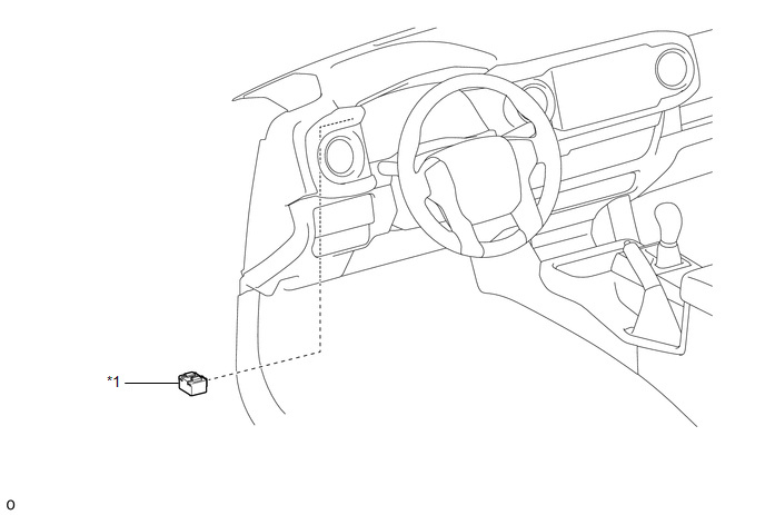
COMPONENTS
ILLUSTRATION
|
*1 |
SKID CONTROL BUZZER |
- |
- |
Inspection
INSPECTION
PROCEDURE
1. INSPECT SKID CONTROL BUZZER
|
(a) Make sure that there is no looseness in the locking part and connecting part of the connector. |
|
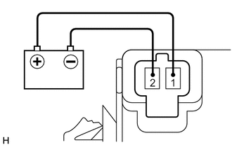
(b) Disconnect the skid control buzzer connector.
(c) Check the connector and terminals for deformation and corrosion.
OK:
No deformation or corrosion.
(d) Connect a positive (+) lead from the battery to terminal 1, and a negative (-) lead to terminal 2 of the skid control buzzer, and check that the buzzer sounds.
OK:
The skid control buzzer sounds.
If the result is not as specified, replace the skid control buzzer.
Removal
REMOVAL
PROCEDURE
1. REMOVE SKID CONTROL BUZZER
|
(a) Disengage the clamp. |
|
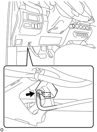
(b) Disconnect the connector to remove the skid control buzzer.
NOTICE:
If the skid control buzzer has been struck or dropped, replace it with a new one.
Installation
INSTALLATION
PROCEDURE
1. INSTALL SKID CONTROL BUZZER
(a) Connect the connector.
(b) Engage the clamp to install the skid control buzzer.
NOTICE:
If the skid control buzzer has been struck or dropped, replace it with a new one.
HINT:
Make sure to install the skid control buzzer in the correct direction.
 ECU Power Source Circuit
DESCRIPTION
This circuit supplies power to the millimeter wave radar sensor assembly when
the ignition switch is ON.
WIRING DIAGRAM
CAUTION / NOTICE / HINT
NOTICE:
Inspect the fuses for circu ...
 Seat
Seat
...
Other materials:
Parts Location
PARTS LOCATION
ILLUSTRATION
ILLUSTRATION
ILLUSTRATION
ILLUSTRATION
ILLUSTRATION
...
Child restraint systems
A child restraint system for a small child or baby must itself be properly
restrained on the seat with the lap portion of the lap/shoulder belt.
The laws of all 50 states of the U.S.A. and Canada now require the use of child
restraint systems.
Points to remember
Studies have shown that instal ...
Traction Off Switch
Components
COMPONENTS
ILLUSTRATION
Removal
REMOVAL
PROCEDURE
1. REMOVE ROOF CONSOLE BOX ASSEMBLY
(See page )
2. REMOVE A-TRAC SWITCH (TRACTION CONTROL SWITCH)
(a) Disconnect the A-TRAC switch (traction control switch) connector.
(b) Using a screwdriver, detach the 2 claws ...
