Toyota Tacoma (2015-2018) Service Manual: Purge Valve
Components
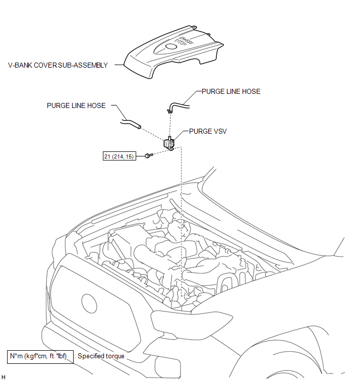
COMPONENTS
ILLUSTRATION
Inspection
INSPECTION
PROCEDURE
1. INSPECT PURGE VSV
|
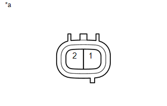
(a) Measure the resistance according to the value(s) in the table below. Text in Illustration
Standard Resistance:
If the result is not as specified, replace the purge VSV. |
|
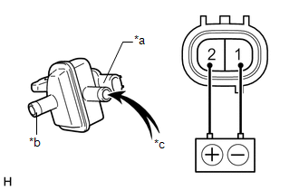
(b) Check the operation of the purge VSV.
|
(1) Apply battery voltage between the terminals of the purge VSV and check that the following occurs when blowing air into the port (E). Text in Illustration
OK:
If the result is not as specified, replace the purge VSV. |
|
Removal
REMOVAL
PROCEDURE
1. REMOVE V-BANK COVER SUB-ASSEMBLY
.gif)
2. REMOVE PURGE VSV
|
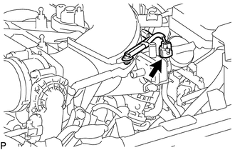
(a) Slide the hose clip and disconnect the purge line hose from the purge VSV. |
|
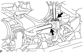
(b) Disconnect the purge line hose from the purge VSV.
|
(c) Disconnect the connector from the purge VSV. |
|
|
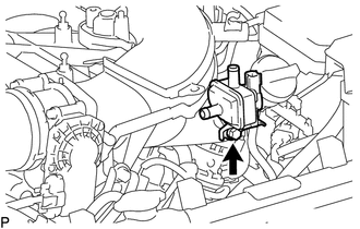
(d) Remove the bolt and purge VSV from the intake air surge tank. |
|
Installation
INSTALLATION
PROCEDURE
1. INSTALL PURGE VSV
(a) Install the purge VSV to the intake air surge tank with the bolt.
Torque:
21 N·m {214 kgf·cm, 15 ft·lbf}
(b) Connect the purge line hose to the purge VSV, and slide the hose clip to secure it.
(c) Connect the purge line hose to the purge VSV.
(d) Connect the connector to the purge VSV.
2. INSTALL V-BANK COVER SUB-ASSEMBLY
.gif)
 Pcv Valve
Components
COMPONENTS
ILLUSTRATION
Inspection
INSPECTION
PROCEDURE
1. INSPECT PCV VALVE SUB-ASSEMBLY
(a) Install a clean hose to the PCV valve sub-assembly.
(b) Check the PCV valve sub-a ...

Other materials:
Evaporator Temperature Sensor Circuit (B1413)
DESCRIPTION
The cooler thermistor sensor (evaporator temperature sensor) is installed on
the evaporator in the air conditioner unit to detect the temperature of the cooled
air that has passed through the evaporator and is used to control the air conditioning.
It sends signals to the air condi ...
System Description
SYSTEM DESCRIPTION
1. SYSTEM DESCRIPTION
HINT:
The skid control ECU is built into the hydraulic brake booster.
(a) ABS (Anti-lock Brake System)
The ABS helps prevent the wheels from locking when the brakes are applied firmly
or when braking on a slippery surface.
(b) Multi-terrain Anti-lock ...
Adjustment
ADJUSTMENT
CAUTION / NOTICE / HINT
CAUTION:
Radiofrequency radiation exposure information:
This equipment complies with FCC radiation exposure limits set forth
for an uncontrolled environment.
This equipment should be kept with minimum distance of 20 cm (7.87 in.)
between the ...
