Toyota Tacoma (2015-2018) Service Manual: Passenger Side Buckle Switch Circuit Malfunction (B1771)
DESCRIPTION
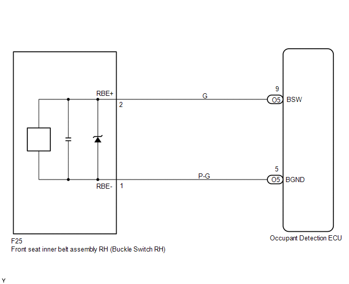
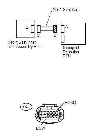
The passenger side buckle switch circuit consists of the occupant detection ECU and the front seat inner belt assembly RH.
DTC B1771 is recorded when a malfunction is detected in the passenger side buckle switch circuit.
Troubleshoot DTC B1771 first when DTCs B1771 and B1795 are output simultaneously.
|
DTC No. |
DTC Detecting Condition |
Trouble Area |
|---|---|---|
|
B1771 |
|
|
HINT:
- When DTC B1650/32 is detected as a result of troubleshooting the supplemental restraint system, perform troubleshooting for DTC B1771 of the occupant classification system.
- Use the Techstream to check for DTCs of the occupant detection ECU, otherwise the DTC cannot be read.
WIRING DIAGRAM
CAUTION / NOTICE / HINT
HINT:
- If troubleshooting (wire harness inspection) is difficult to perform, remove the front passenger seat installation bolts to see the under surface of the seat cushion.
- In the above case, hold the seat so that it does not tip over. Holding the seat for a long period of time may cause a problem, such as seat rail deformation. Hold the seat up only for as long as necessary.
PROCEDURE
|
1. |
CHECK DTC |
(a) Turn the ignition switch to the on position.
(b) Clear the DTCs stored in the memory (See page
.gif) ).
).
HINT:
First clear DTCs stored in the occupant detection ECU and then in the airbag sensor assembly.
(c) Turn the ignition switch to the lock position.
(d) Turn the ignition switch to the on position.
(e) Check the DTCs (See page ).
OK:
DTC B1771 is not output.
HINT:
Codes other than DTC B1771 may be output at this time, but they are not related to this check.
| OK | .gif) |
USE SIMULATION METHOD TO CHECK |
|
.gif)
|
2. |
CHECK CONNECTION OF CONNECTORS |
(a) Turn the ignition switch to the lock position.
(b) Disconnect the negative (-) terminal cable from the battery, and wait for at least 90 seconds.
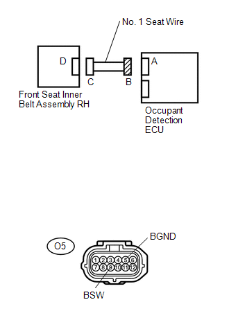
(c) Check that the connectors are properly connected to the occupant detection ECU and the front seat inner belt assembly RH.
OK:
The connectors are properly connected.
| NG | |
CONNECT CONNECTORS |
|
|
3. |
CHECK CONNECTORS |
(a) Check that the connectors (on the occupant detection ECU side and buckle
switch RH side) are not damaged (See page ).
OK:
The connectors are not deformed or damaged.
| NG | |
REPAIR OR REPLACE WIRE HARNESS |
|
|
4. |
CHECK NO. 1 SEAT WIRE (TO B+) |
|
(a) Disconnect the connectors from the occupant detection ECU and the front seat inner belt assembly RH. |
|
(b) Connect the negative (-) terminal cable to the battery.
(c) Turn the ignition switch to the on position.
(d) Measure the voltage.
Standard voltage:
|
Tester connection |
Condition |
Specified condition |
|---|---|---|
|
O5-9 (BSW) - Body ground |
Ignition switch on |
Below 1 V |
|
O5-5 (BGND) - Body ground |
Ignition switch on |
Below 1 V |
| NG | |
REPAIR OR REPLACE NO. 1 SEAT WIRE |
|
|
5. |
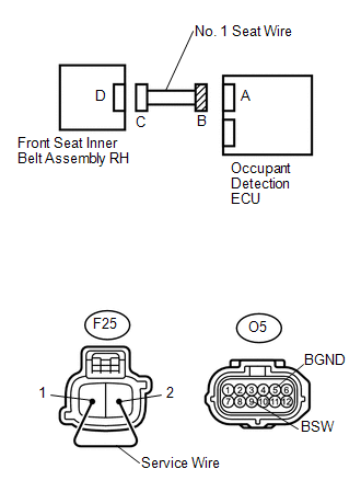
CHECK NO. 1 SEAT WIRE (FOR OPEN) |
|
(a) Turn the ignition switch to the lock position. |
|
(b) Disconnect the negative (-) terminal cable from the battery, and wait for at least 90 seconds.
(c) Using a service wire, connect J11-2 and J11-1 of connector C.
NOTICE:
Do not forcibly insert a service wire into the terminals of the connector when connecting.
(d) Measure the resistance.
Standard resistance:
|
Tester connection |
Condition |
Specified condition |
|---|---|---|
|
O5-9 (BSW) - O5-5 (BGND) |
Always |
Below 1 Ω |
| NG | |
REPAIR OR REPLACE NO. 1 SEAT WIRE |
|
|
6. |
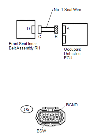
CHECK NO. 1 SEAT WIRE (FOR SHORT) |
|
(a) Disconnect the service wire from connector C. |
|
(b) Measure the resistance.
Standard resistance:
|
Tester connection |
Condition |
Specified condition |
|---|---|---|
|
O5-9 (BSW) - O5-5 (BGND) |
Always |
1 MΩ or higher |
| NG | |
REPAIR OR REPLACE NO. 1 SEAT WIRE |
|
|
7. |
CHECK NO. 1 SEAT WIRE (TO GROUND) |
|
(a) Measure the resistance. Standard resistance:
|
|
| NG | |
REPAIR OR REPLACE NO. 1 SEAT WIRE |
|
|
8. |
CHECK DTC |
(a) Connect the connectors to the occupant detection ECU and the front seat inner belt assembly RH.
(b) Connect the negative (-) terminal cable to the battery.
(c) Turn the ignition switch to the on position.
(d) Clear the DTCs stored in the memory (See page
).
HINT:
First clear DTCs stored in the occupant detection ECU and then in the airbag sensor assembly.
(e) Turn the ignition switch to the lock position.
(f) Turn the ignition switch to the on position.
(g) Check the DTCs (See page ).
OK:
DTC B1771 is not output.
HINT:
Codes other than DTC B1771 may be output at this time, but they are not related to this check.
| OK | |
USE SIMULATION METHOD TO CHECK |
|
|
9. |
REPLACE FRONT SEAT INNER BELT ASSEMBLY RH |
(a) Turn the ignition switch to the lock position.
(b) Disconnect the negative (-) terminal cable from the battery, and wait for at least 90 seconds.
(c) Replace the front seat inner belt assembly RH (See page
).
HINT:
Perform the inspection using parts from a normal vehicle if possible.
(d) Connect the negative (-) terminal cable to the battery.
(e) Turn the ignition switch to the on position.
(f) Clear the DTCs stored in the memory (See page
).
HINT:
First clear DTCs stored in the occupant detection ECU and then in the airbag sensor assembly.
(g) Turn the ignition switch to the lock position.
(h) Turn the ignition switch to the on position.
(i) Check the DTCs (See page ).
OK:
DTC B1771 is not output.
HINT:
Codes other than DTC B1771 may be output at this time, but they are not related to this check.
| OK | |
END |
|
|
10. |
REPLACE OCCUPANT DETECTION ECU |
(a) Turn the ignition switch to the lock position.
(b) Disconnect the negative (-) terminal cable from the battery, and wait for at least 90 seconds.
(c) Replace the occupant detection ECU (See page
).
|
|
11. |
PERFORM ZERO POINT CALIBRATION |
(a) Connect the negative (-) terminal cable to the battery.
(b) Connect the Techstream to the DLC3.
(c) Turn the ignition switch to the on position.
(d) Using the Techstream, perform the zero point calibration (See page
).
OK:
"Zero Point Calibration is complete." is displayed on the Techstream.
|
|
12. |
PERFORM SENSITIVITY CHECK |
(a) Using the Techstream, perform the sensitivity check (See page
).
Standard values:
27 to 33 kg (59.52 to 72.75 lb)
| NEXT | |
END |
 Front Occupant Classification Sensor RH Collision Detection (B1786)
DESCRIPTION
DTC B1786 is set when the occupant detection ECU receives a collision detection
signal, which is sent by the front occupant classification sensor RH when an accident
occurs.
DTC B178 ...
 Front Occupant Classification Sensor RH Circuit Malfunction (B1781)
DESCRIPTION
The front occupant classification sensor RH circuit consists of the occupant
detection ECU and the front occupant classification sensor RH.
DTC B1781 is set when a malfunction is detec ...
Other materials:
Engine Switch Illumination Circuit
DESCRIPTION
The illuminated entry system controls the engine switch illumination.
WIRING DIAGRAM
PROCEDURE
1.
READ VALUE USING TECHSTREAM (POWER/ENGINE SW LIGHT)
(a) Connect the Techstream to the DLC3.
(b) Turn the engine switch to ON.
(c) Turn the Techstream ...
Speed Signal Malfunction (B15C2)
DESCRIPTION
The navigation receiver assembly receives a vehicle speed signal from the combination
meter assembly and information from the navigation antenna assembly, and then adjusts
the vehicle position.
The navigation receiver assembly stores this DTC when the difference between
the speed ...
Installation
INSTALLATION
PROCEDURE
1. INSTALL COOLER (ROOM TEMPERATURE SENSOR) THERMISTOR
(a) Connect the cooler air hose.
(b) Connect the connector.
(c) Engage the 2 claws to connect the cooler (room temperature sensor ) thermistor.
2. INSTALL INSTRUMENT PANEL LOWER FINISH PANEL SUB-ASSEMBLY RH
3. I ...
