PARTS LOCATION
ILLUSTRATION
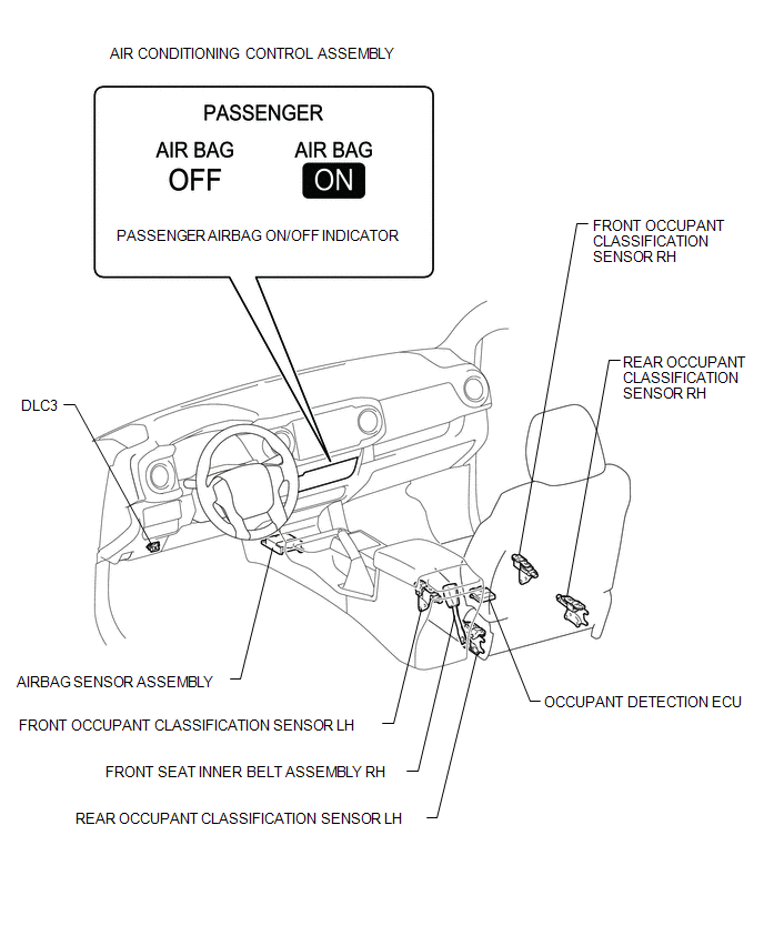
Related Tacoma materials
Tire inflation pressure
■ Tire inflation pressure
The recommended cold tire inflation pressure and tire size is displayed on the
tire and loading information label.
Regular Cab and Double Cab models
Access Cab models
...
CD cannot be Ejected
PROCEDURE
1.
CHECK OPERATION
(a) Press the disc eject switch of the radio and display receiver assembly for
5 seconds or more and check that the CD is ejected.
OK:
CD is ejected.
NG
...
Black Screen
PROCEDURE
1.
CHECK DISPLAY SETTING
(a) Check that the display is not in "Screen Off" mode.
OK:
The display setting is not in "Screen Off" mode.
NG
CH ...