Toyota Tacoma (2015-2018) Service Manual: Parts Location
PARTS LOCATION
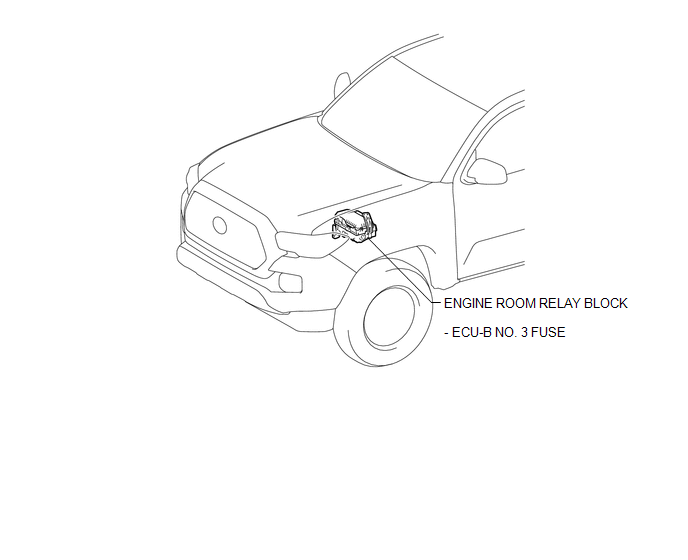
ILLUSTRATION
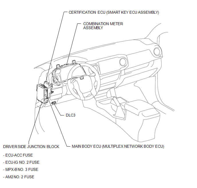
ILLUSTRATION
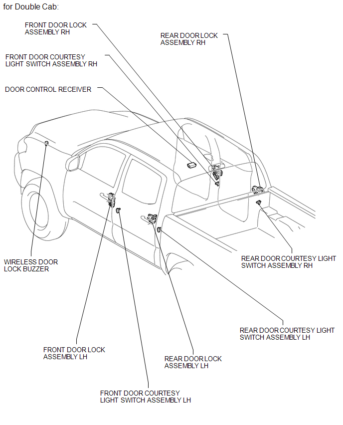
ILLUSTRATION
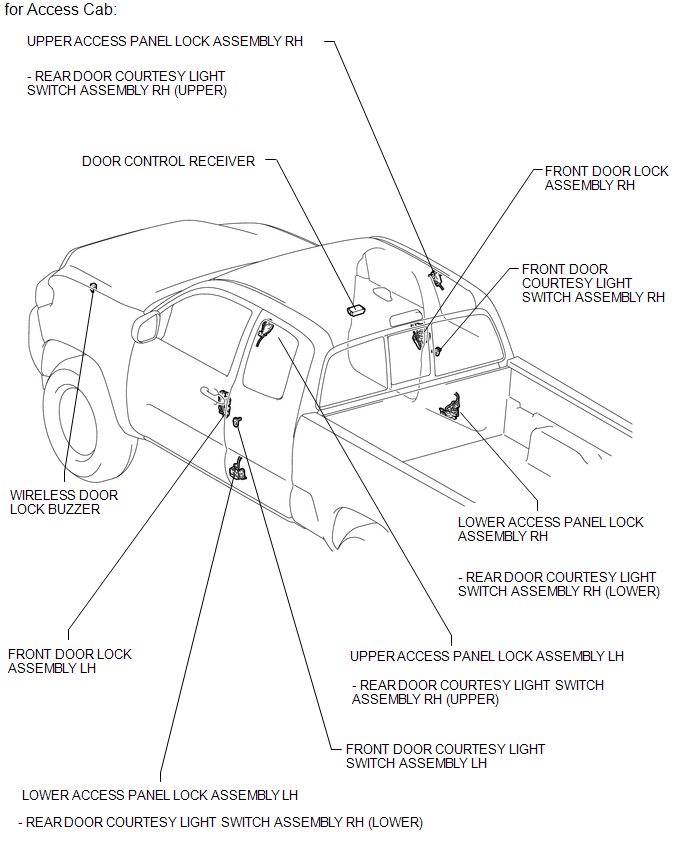
ILLUSTRATION

 Precaution
PRECAUTION
1. PRECAUTIONS WHEN USING TECHSTREAM
(a) When using the Techstream with the engine switch off to troubleshoot:
Connect the Techstream to the vehicle, and turn a courtesy light switch on ...
Other materials:
Inside Vehicle
General Maintenance
GENERAL MAINTENANCE
CAUTION / NOTICE / HINT
Performing these maintenance checks on the vehicle is the owner's responsibility.
The owner may perform the maintenance or take the vehicle to a service center.
Check the parts of the vehicle described below on a daily basis ...
System Description
SYSTEM DESCRIPTION
1. NAVIGATION SYSTEM OUTLINE
(a) Vehicle position tracking methods
It is essential that the navigation system correctly tracks the current vehicle
position and displays it on the map. There are 2 methods to track the current vehicle
position: autonomous (dead reckoning) and ...
Installation
INSTALLATION
PROCEDURE
1. INSTALL TRANSFER POSITION SWITCH (for 4WD)
Click here
2. INSTALL ENGINE SWITCH
Click here
3. INSTALL AIR CONDITIONING CONTROL ASSEMBLY
(a) Connect the connectors.
(b) Engage the 8 clips to install the air conditioning control assembly.
4. INSTALL RADIO AND DISP ...
