Toyota Tacoma (2015-2018) Service Manual: Parts Location
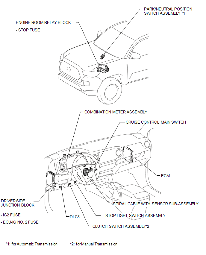
PARTS LOCATION
ILLUSTRATION
 Precaution
PRECAUTION
HANDLING PRECAUTION FOR CRUISE CONTROL SYSTEM
(a) Turn the cruise control system off using the cruise control main switch (ON-OFF
button) when not using the cruise control system.
(b) ...
 System Description
SYSTEM DESCRIPTION
1. CRUISE CONTROL SYSTEM
The cruise control system makes it possible to drive at a desired speed without
using the accelerator pedal. ECM controls the throttle opening angle bas ...
Other materials:
Switch Failure (B2342)
DESCRIPTION
This DTC is stored when the sliding roof ECU (sliding roof drive gear sub-assembly)
detects that the sliding roof switch is stuck for 30 seconds or more.
DTC No.
DTC Detection Condition
Trouble Area
B2342
Sliding roof ECU ( ...
TS and CG Terminal Circuit
DESCRIPTION
In Test Mode (signal check), a malfunction in the speed sensor that cannot be
detected when the vehicle is stopped can be detected while driving.
Sensor check mode can be entered by connecting terminals TS and CG of the DLC3
and turning the ignition switch from off to ON.
WIRING D ...
Removal
REMOVAL
CAUTION / NOTICE / HINT
HINT:
Use the same procedure for both the LH and RH sides.
The procedure described below is for the LH side.
PROCEDURE
1. REMOVE FRONT BUMPER ASSEMBLY
(See page
)
2. REMOVE HEADLIGHT ASSEMBLY
(a) Apply protective tape around the headlight ...
