PARTS LOCATION
ILLUSTRATION
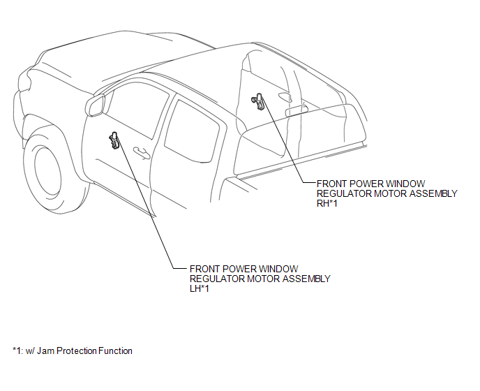
ILLUSTRATION
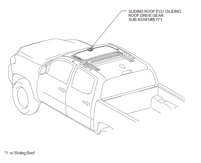
ILLUSTRATION
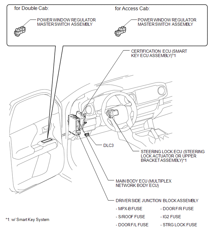
Related Tacoma materials
Main Body ECU Vehicle Information Reading/Writing Process Malfunction (B15F6)
DESCRIPTION
This DTC is stored when items controlled by the main body ECU cannot be customized
via the navigation system vehicle customization screen.
HINT:
The main body ECU controls the items for the following systems that are customizable
via the navigation receiver assembly screen:
...
Precaution
PRECAUTION
1. IGNITION SWITCH EXPRESSION
(a) The type of ignition switch used on this model differs depending on the specifications
of the vehicle. The expressions listed in the table below are used in this section.
Expression
Ignition Switch (Position)
...
Inspection
INSPECTION
PROCEDURE
1. INSPECT INPUT SHAFT
(a) Using a dial indicator and 2 V-blocks, measure the shaft runout.
Maximum runout:
0.03 mm (0.0012 in.)
If the runout is more than the maximum, replace the input shaft.
HINT:
Measure the 3 areas shown in the illustration wit ...