Toyota Tacoma (2015-2018) Service Manual: Parking Brake Switch Circuit
DESCRIPTION
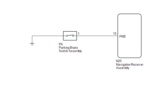
This circuit is from the parking brake switch assembly to the navigation receiver assembly.
WIRING DIAGRAM
PROCEDURE
|
1. |
CHECK VEHICLE SIGNAL (OPERATION CHECK) |
|
(a) Display the "Vehicle Signal Check Mode" screen (See page
|
|
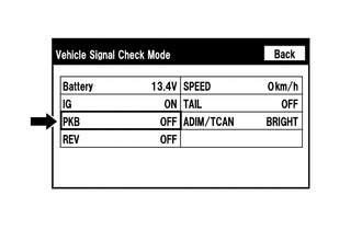
(b) Check that the display changes between ON and OFF according to the parking brake operation.
OK:
|
Parking Brake Condition |
Display |
|---|---|
|
Applied |
ON |
|
Released |
OFF |
HINT:
This display is updated once per second. As a result, it is normal for the display to lag behind the actual parking brake operation.
| OK | .gif) |
PROCEED TO NEXT SUSPECTED AREA SHOWN IN PROBLEM SYMPTOMS TABLE |
|
.gif)
|
2. |
CHECK HARNESS AND CONNECTOR (NAVIGATION RECEIVER ASSEMBLY - PARKING BRAKE SWITCH ASSEMBLY) |
(a) Disconnect the N25 navigation receiver assembly connector.
(b) Disconnect the P6 parking brake switch assembly connector.
(c) Measure the resistance according to the value(s) in the table below.
Standard Resistance:
|
Tester Connection |
Condition |
Specified Condition |
|---|---|---|
|
N25-15 (PKB) - P6-1 |
Always |
Below 1 Ω |
|
N25-15 (PKB) - Body ground |
Always |
10 kΩ or higher |
| NG | |
REPAIR OR REPLACE HARNESS OR CONNECTOR |
|
|
3. |
INSPECT PARKING BRAKE SWITCH ASSEMBLY |
(a) Remove the parking brake switch assembly.
(b) Inspect the parking brake switch assembly.
- for Hydraulic Brake Booster: See page
.gif)
- for Vacuum Brake Booster: See page
| OK | |
PROCEED TO NEXT SUSPECTED AREA SHOWN IN PROBLEM SYMPTOMS TABLE |
| NG | |
REPLACE PARKING BRAKE SWITCH ASSEMBLY |
 Illumination Circuit
DESCRIPTION
Power is supplied to the navigation receiver assembly and steering pad switch
assembly illumination when the light control switch is in the TAIL or HEAD position.
WIRING DIAGRAM
CAU ...
 Speaker Circuit
DESCRIPTION
If there is a short in a speaker circuit, the stereo component amplifier assembly*1
or navigation receiver assembly*2 detects it and stops output to the speakers.
Thus sound cannot be ...
Other materials:
Route cannot be Calculated
PROCEDURE
1.
SET DESTINATION
(a) Set another destination and check if the system can calculate the route correctly.
OK:
Route can be correctly calculated.
OK
NORMAL OPERATION
NG
PROCEED TO NEXT SUSPECTED AREA SHOWN ...
Disassembly
DISASSEMBLY
PROCEDURE
1. REMOVE CYLINDER BOOT
(a) Using a screwdriver, remove the 4 cylinder boots from the caliper.
2. REMOVE FRONT DISC BRAKE PISTON
(a) Prepare a wooden plate to hold the pistons.
(b) Place the plate between the pistons and insert a pad into one side.
...
Installation
INSTALLATION
PROCEDURE
1. INSTALL OCCUPANT DETECTION ECU
(a) Check that the ignition switch is OFF.
(b) Check that the cable is disconnected from the battery negative (-) terminal
is disconnected.
CAUTION:
After removing the cable from the terminal, wait for at least 90 seconds before
star ...
