Toyota Tacoma (2015-2018) Service Manual: Panel Switches do not Function
PROCEDURE
|
1. |
CHECK PANEL SWITCH |
(a) Check for foreign matter around the switches that might prevent operation.
OK:
No foreign matter is found.
| NG | .gif) |
REMOVE ANY FOREIGN MATTER FOUND |
|
.gif)
|
2. |
CHECK PANEL SWITCH (OPERATION CHECK) |
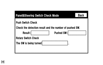
(a) Enter the "Panel & Steering Switch Check Mode" screen. Refer to Check Panel
& Steering Switch in Operation Check (See page .gif) ).
).
(b) Operate the abnormal switch and check if the switch status is correctly displayed.
OK:
The switch status is correctly displayed as operated.
| OK | |
REPLACE RADIO AND DISPLAY RECEIVER ASSEMBLY |
| NG | |
PROCEED TO NEXT SUSPECTED AREA SHOWN IN PROBLEM SYMPTOMS TABLE |
 Display does not Dim when Light Control Switch is Turned ON
PROCEDURE
1.
CHECK IMAGE QUALITY SETTING
(a) Display the "Display" screen.
(b) Turn the light control switch to the tail or head position.
(c) Check if &q ...
 Touch Panel Switch does not Function
PROCEDURE
1.
CHECK MULTI-DISPLAY
(a) Check if there is any foreign matter caught between the display and exterior
frame of the multi-display.
OK:
No foreign matt ...
Other materials:
On-vehicle Inspection
ON-VEHICLE INSPECTION
PROCEDURE
1. INSPECT SIDE AIRBAG SENSOR ASSEMBLY (for Vehicle not Involved in Collision)
(a) Perform a diagnostic system check (See page
).
2. INSPECT SIDE AIRBAG SENSOR ASSEMBLY (for Vehicle Involved in Collision and
Airbag has not Deployed)
(a) Perform a diagnostic s ...
Installation
INSTALLATION
PROCEDURE
1. INSTALL POWER STEERING LINK
(a) Insert the power steering link into the vehicle in the order shown in the
illustration.
Install in this Direction (1)
Install in this Direction (2)
(b) Using SST, inst ...
Disassembly
DISASSEMBLY
PROCEDURE
1. REMOVE STEERING INTERMEDIATE SHAFT ASSEMBLY
(a) Put matchmarks on the steering intermediate shaft assembly and steering main
shaft assembly.
(b) Remove the bolt and steering intermediate shaft assembly.
2. REMOVE UPPER STEERING COLUMN BRACKET WITH SWITCH ASSEMBLY (w ...
