Toyota Tacoma (2015-2018) Service Manual: Operation Check
OPERATION CHECK
1. CHECK WIRELESS CHARGING SYSTEM OPERATION
(a) Turn the ignition switch ON (IG or ACC).
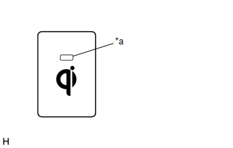
(b) Press the mobile wireless charger switch and check that the switch indicator light illuminates.
 Text in Illustration
|
*a |
Switch Indicator Light |
(c) Place a rechargeable device on the charging area and check that the indicator light (amber) illuminates, indicating a charge is in progress.
.png) Text in Illustration
Text in Illustration
|
*a |
Indicator Light (Green) |
|
*b |
Indicator Light (Amber) |
|
*c |
Charging Area |
(d) Check that the indicator lights (amber and green) are illuminated when charging is complete.
HINT:
- Some phones, cases or cover type wireless chargers may not cause the green indicator to illuminate even though it is fully charged.
- Check the mobile device to confirm charge status.
HINT:
Please refer to precaution for the details (See page
.gif) ).
).
 How To Proceed With Troubleshooting
CAUTION / NOTICE / HINT
HINT:
Use the following procedure to troubleshoot the wireless charging system.
PROCEDURE
1.
VEHICLE BROUGHT TO WORKSHOP
...
 Problem Symptoms Table
PROBLEM SYMPTOMS TABLE
HINT:
Use the table below to help determine the cause of problem symptoms.
If multiple suspected areas are listed, the potential causes of the symptoms
are lis ...
Other materials:
Lost Communication with Alternator Missing Message (P161A87)
DESCRIPTION
The ECM communicates with the generator assembly via LIN communication. If a
LIN communication error is detected, the ECM stores this DTC.
DTC No.
DTC Detection Condition
Trouble Area
P161A87
Generator assembly or ECM commu ...
Customize Parameters
CUSTOMIZE PARAMETERS
1. LANE DEPARTURE ALERT SYSTEM
Click here
2. INTUITIVE PARKING ASSIST SYSTEM
Click here
3. PRE-COLLISION SYSTEM
Click here
4. SEAT BELT WARNING SYSTEM
Click here
5. AIR CONDITIONING SYSTEM (for Automatic Air Conditioning System)
Click here
6. THEFT DETERRENT ...
Rear Speed Sensor RH Output Malfunction (C1415,C1416)
DESCRIPTION
Refer to DTCs C1403 and C1404 (See page ).
DTC No.
Detection Item
DTC Detection Condition
Trouble Area
C1415
Rear Speed Sensor RH Output Malfunction
Any of the following is detected:
An op ...
