Toyota Tacoma (2015-2018) Service Manual: On-vehicle Inspection
ON-VEHICLE INSPECTION
PROCEDURE
1. INSPECT RADIATOR CAP SUB-ASSEMBLY
CAUTION:
Do not remove the radiator cap sub-assembly while the engine and radiator assembly are still hot. Pressurized, hot engine coolant and steam may be released and cause serious burns.
(a) Measure the valve opening pressure.
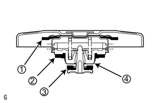
(1) If there are water stains or foreign matter on rubber packing 1, 2 or 3, clean it by using water and finger scouring.
(2) Check that rubber packing 1, 2 and 3 are not deformed, cracked or swollen.
(3) Check that rubber packing 3 and 4 are not stuck together.
(4) Apply engine coolant to rubber packing 2 and 3.
|
(5) When using the radiator cap tester, tilt it 30° or more. Text in Illustration
|
|
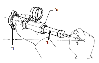
(6) Pump the radiator cap tester several times and check the maximum pressure.*1
Pumping speed:
1 pump per second
HINT:
*1: Even if the radiator cap sub-assembly cannot maintain the maximum pressure, it is not necessarily defective.
Standard Judgment Criterion:
|
Item |
Specified Condition |
|---|---|
|
Standard value (for brand-new cap) |
93 to 123 kPa (1.0 to 1.3 kgf/cm2, 14 to 18 psi) |
|
Minimum standard value (for used cap) |
79 kPa (0.8 kgf/cm2, 11 psi) |
If the maximum pressure is less than the minimum standard value, replace the radiator cap sub-assembly.
2. INSPECT FINS FOR BLOCKAGE
|
(a) If the fins are clogged, wash them with water or a steam cleaner and dry them with compressed air. NOTICE:
|
|
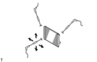
(b) Dry the fins with compressed air.
 Components
COMPONENTS
ILLUSTRATION
ILLUSTRATION
ILLUSTRATION
...
 Disassembly
DISASSEMBLY
PROCEDURE
1. REMOVE RADIATOR DRAIN COCK PLUG
(a) Remove the radiator drain cock plug from the radiator assembly.
(b) Remove the O-ring from the radiator drain cock plug.
2. REMOVE RAD ...
Other materials:
No Sound can be Heard from Speakers
PROCEDURE
1.
CHECK AUDIO SETTINGS
(a) Display the "Sound Settings" screen.
(b) Set volume, fader and balance to the initial values and check that sound
is normal.
OK:
Audio system returns to normal.
HINT:
Sound quality adjustment measures vary acco ...
Chassis
General Maintenance
GENERAL MAINTENANCE
PROCEDURE
1. INSPECT STEERING LINKAGE
(a) Check the steering wheel free play (See page
).
(b) Check the steering linkage for looseness or damage.
(1) Check that the tie rod ends do not have excessive play.
(2) Check that the dust seals and boots are ...
Clutch Accumulator
Components
COMPONENTS
ILLUSTRATION
Installation
INSTALLATION
PROCEDURE
1. INSTALL CLUTCH ACCUMULATOR ASSEMBLY
(a) Install the clutch accumulator assembly to the manual transmission assembly
with the 3 bolts.
Torque:
12 N·m {120 kgf·cm, 9 ft·lbf}
(b) Using a union nut wrench, co ...
