Toyota Tacoma (2015-2018) Service Manual: Removal
REMOVAL
PROCEDURE
1. REMOVE LOWER STEERING COLUMN COVER
.gif)
2. REMOVE UPPER STEERING COLUMN COVER
3. REMOVE WINDSHIELD WIPER SWITCH ASSEMBLY
|
(a) Disconnect the 2 connectors. Text in Illustration
|
|
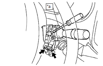
(b) Using a screwdriver with its tip wrapped in protective tape, disengage the claw to remove the windshield wiper switch assembly.
NOTICE:
If the claw is pulled with excessive force, it may break.
 On-vehicle Inspection
ON-VEHICLE INSPECTION
PROCEDURE
1. INSPECT WINDSHIELD WIPER SWITCH ASSEMBLY (w/ Intermittent function)
(a) Remove the steering column cover.
(b) Check the front wiper intermittent operation.
Tex ...
 Inspection
INSPECTION
PROCEDURE
1. INSPECT WINDSHIELD WIPER SWITCH ASSEMBLY
(a) Check the resistance.
Text in Illustration
*a
Component without harness conne ...
Other materials:
Power Source Circuit
DESCRIPTION
This circuit provides power to operate the forward recognition camera.
WIRING DIAGRAM
CAUTION / NOTICE / HINT
NOTICE:
Inspect the fuses for circuits related to this system before performing the following
inspection procedure.
PROCEDURE
1.
CHECK HARNESS A ...
Terminals Of Ecu
TERMINALS OF ECU
Text in Illustration
*a
Component without harness connected
(Skid Control ECU [Brake Actuator Assembly])
-
-
Terminal No. (Symbol)
Terminal Description
1 (GND2)
Pump motor g ...
Illumination Circuit
DESCRIPTION
Power is supplied to the navigation receiver assembly and steering pad switch
assembly illumination when the light control switch is in the TAIL or HEAD position.
WIRING DIAGRAM
CAUTION / NOTICE / HINT
NOTICE:
The vehicle is equipped with a Supplemental Restraint System ...
