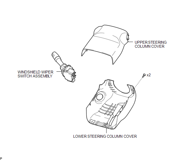
COMPONENTS
ILLUSTRATION
Related Tacoma materials
Bottle holders
Front
Front console box (Separated type
front seat)
Rear (Double Cab models)
...
Radio Receiver
Components
COMPONENTS
ILLUSTRATION
ILLUSTRATION
Removal
REMOVAL
PROCEDURE
1. REMOVE INSTRUMENT CLUSTER CENTER FINISH PANEL SUB-ASSEMBLY
( ...
Open in Outer Mirror Indicator(Slave) (C1AB5)
DESCRIPTION
This DTC is stored when the blind spot monitor sensor RH detects an open in the
blind spot monitor indicator RH.
DTC Code
DTC Detection Condition
Trouble Area
C1AB5
...