DESCRIPTION
The radio and display receiver assembly and telephone microphone assembly are connected to each other using the microphone connection detection signal lines.
Using this circuit, the radio and display receiver assembly sends power to the telephone microphone assembly, and the telephone microphone assembly sends microphone signals to the radio and display receiver assembly.
WIRING DIAGRAM
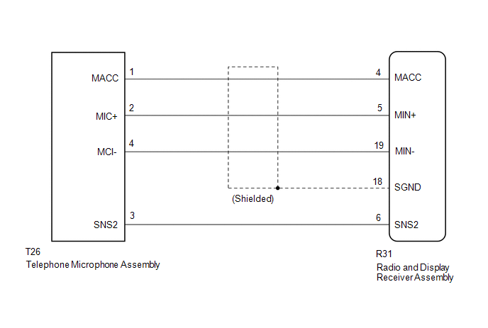
PROCEDURE
|
1. |
CHECK MICROPHONE |
|
(a) Enter the "Microphone Check" screen. Refer to Check Microphone in Operation Check. Click here |
|
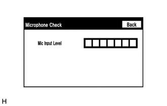
(b) When a voice is input into the microphone, check that the microphone input level meter changes according to the input voice.
OK:
Check result is normal.
| OK | .gif) |
PROCEED TO NEXT SUSPECTED AREA SHOWN IN PROBLEM SYMPTOMS TABLE |
|
.gif)
|
2. |
CHECK HARNESS AND CONNECTOR (RADIO AND DISPLAY RECEIVER ASSEMBLY - TELEPHONE MICROPHONE ASSEMBLY |
(a) Disconnect the R31 radio and display receiver assembly connector.
(b) Disconnect the T26 telephone microphone assembly connector.
(c) Measure the resistance according to the value(s) in the table below.
Standard Resistance:
|
Tester Connection |
Condition |
Specified Condition |
|---|---|---|
|
R31-4 (MACC) - T26-1 (MACC) |
Always |
Below 1 Ω |
|
R31-5 (MIN+) - T26-2 (MIC+) |
Always |
Below 1 Ω |
|
R31-19 (MIN-) - T26-4 (MIC-) |
Always |
Below 1 Ω |
|
R31-6 (SNS2) - T26-3 (SNS2) |
Always |
Below 1 Ω |
|
R31-4 (MACC) - Body ground |
Always |
10 kΩ or higher |
|
R31-5 (MIN+) - Body ground |
Always |
10 kΩ or higher |
|
R31-19 (MIN-) - Body ground |
Always |
10 kΩ or higher |
|
R31-18 (SGND) - Body ground |
Always |
10 kΩ or higher |
|
R31-6 (SNS2) - Body ground |
Always |
10 kΩ or higher |
(d) Reconnect the radio and display receiver assembly connector.
(e) Reconnect the telephone microphone assembly connector.
| NG | |
REPAIR OR REPLACE HARNESS OR CONNECTOR |
|
|
3. |
INSPECT RADIO AND DISPLAY RECEIVER ASSEMBLY |
(a) Remove the radio and display receiver assembly with connectors still connected.
|
(b) Measure the voltage according to the value(s) in the table below. Standard Voltage:
|
|
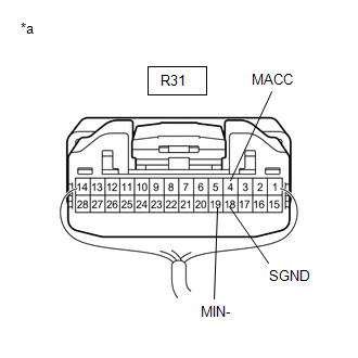
(c) Measure the resistance according to the value(s) in the table below.
Standard Resistance:
|
Tester Connection |
Condition |
Specified Condition |
|---|---|---|
|
R31-19 (MIN-) - Body ground |
Always |
Below 1 Ω |
|
R31-18 (SGND) - Body ground |
Always |
Below 1 Ω |
| NG | |
REPLACE RADIO AND DISPLAY RECEIVER ASSEMBLY |
|
|
4. |
INSPECT TELEPHONE MICROPHONE ASSEMBLY |
|
(a) Remove the telephone microphone assembly. Click here |
|
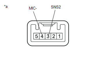
(b) Measure the resistance according to the value(s) in the table below.
Standard Resistance:
|
Tester Connection |
Condition |
Specified Condition |
|---|---|---|
|
3 (SNS2) - 4 (MIC-) |
Always |
Below 1 Ω |
(c) Install the telephone microphone assembly.
Click here .gif)
| NG | |
REPLACE TELEPHONE MICROPHONE ASSEMBLY |
|
|
5. |
INSPECT TELEPHONE MICROPHONE ASSEMBLY |
|
(a) Turn the ignition switch to ACC. |
|
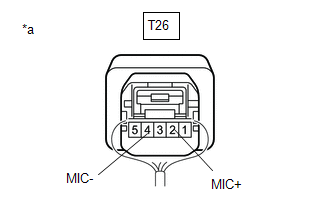
(b) Connect an oscilloscope to terminals 2 (MIC+) and 4 (MIC-) of the telephone microphone assembly connector.
(c) Check the waveform of the telephone microphone assembly using the oscilloscope.
Result|
Result |
Proceed to |
|---|---|
|
A waveform synchronized with the voice input to the amplifier microphone assembly is output |
A |
|
A waveform synchronized with the voice input to the amplifier microphone assembly is not output |
B |
| A | |
PROCEED TO NEXT SUSPECTED AREA SHOWN IN PROBLEM SYMPTOMS TABLE |
| B | |
REPLACE TELEPHONE MICROPHONE ASSEMBLY |