DESCRIPTION
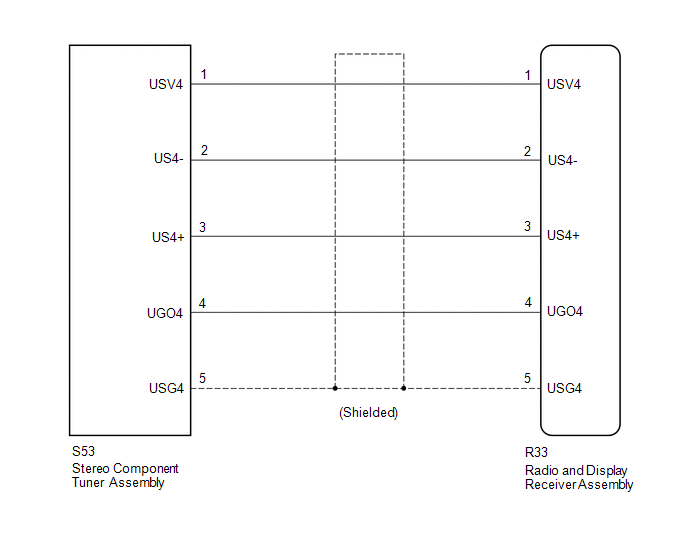
The stereo component tuner assembly sends the image data signal to the radio
and display receiver assembly via this circuit.
WIRING DIAGRAM
PROCEDURE
|
1.
|
CHECK NO. 1 NAVIGATION WIRE
|
(a) Disconnect the R33 radio and display receiver assembly connector.
(b) Disconnect the S53 stereo component tuner assembly connector.
|
(c) Measure the resistance according to the value(s) in the table below.
Standard Resistance:
|
Tester Connection
|
Condition
|
Specified Condition
|
|
S53-1 (USV4) - R33-1 (USV4)
|
Always
|
Below 1 Ω
|
|
S53-2 (US4-) - R33-2 (US4-)
|
Always
|
Below 1 Ω
|
|
S53-3 (US4+) - R33-3 (US4+)
|
Always
|
Below 1 Ω
|
|
S53-4 (UGO4) - R33-4 (UGO4)
|
Always
|
Below 1 Ω
|
|
S53-5 (USG4) - R33-5 (USG4)
|
Always
|
Below 1 Ω
|
|
S53-1 (USV4) - Body ground
|
Always
|
10 kΩ or higher
|
|
S53-2 (US4-) - Body ground
|
Always
|
10 kΩ or higher
|
|
S53-3 (US4+) - Body ground
|
Always
|
10 kΩ or higher
|
|
S53-4 (UGO4) - Body ground
|
Always
|
10 kΩ or higher
|
|
S53-5 (USG4) - Body ground
|
Always
|
10 kΩ or higher
|
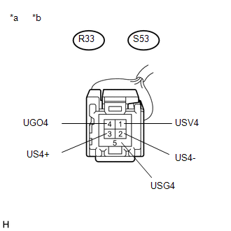
Text in Illustration
|
*a
|
Front view of No. 1 navigation wire connector
(to Radio and Display Receiver Assembly)
|
|
*b
|
Front view of No. 1 navigation wire connector
(to Stereo Component Tuner Assembly)
|
|
|
| OK |
|
PROCEED TO NEXT SUSPECTED AREA SHOWN IN PROBLEM SYMPTOMS TABLE
|
| NG |
|
REPLACE NO. 1 NAVIGATION WIRE
|
DESCRIPTION
The No. 1 stereo jack adapter assembly sends the sound data signal or image data
signal from a USB device to the radio and display receiver assembly via this circuit.
WIRING DIAGRAM
...
DESCRIPTION
The radio and display receiver assembly and telephone microphone assembly are
connected to each other using the microphone connection detection signal lines.
Using this circuit, the ra ...