Toyota Tacoma (2015-2018) Service Manual: LVDS Signal Malfunction (from Extension Module) (B1532)
DESCRIPTION
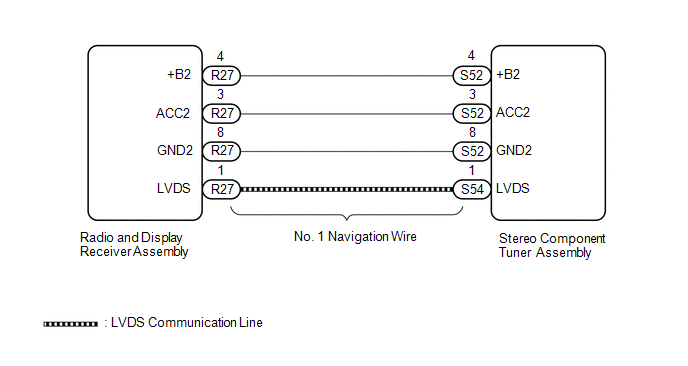
The stereo component tuner assembly and the radio and display receiver assembly are connected by an LVDS communication line.
This DTC is stored when an LVDS communication error occurs between the stereo component tuner assembly and the radio and display receiver assembly.
|
DTC Code |
DTC Detection Condition |
Trouble Area |
|---|---|---|
|
B1532 |
When any of the following conditions is met:
|
|
HINT:
Even if no malfunction is present, this DTC may be stored depending on the battery condition or engine start voltage.
WIRING DIAGRAM
CAUTION / NOTICE / HINT
NOTICE:
After replacing the stereo component tuner assembly of vehicles subscribed to pay-type satellite radio broadcasts, XM radio ID registration is necessary.
PROCEDURE
|
1. |
CHECK NO. 1 NAVIGATION WIRE (STEREO COMPONENT TUNER ASSEMBLY POWER SOURCE) |
|
(a) Disconnect the stereo component tuner assembly connector. |
|
(b) Measure the resistance according to the value(s) in the table below.
Standard Resistance:
|
Tester Connection |
Condition |
Specified Condition |
|---|---|---|
|
S52-8 (GND2) - Body ground |
Always |
Below 1 Ω |
(c) Measure the voltage according to the value(s) in the table below.
Standard Voltage:
|
Tester Connection |
Switch Condition |
Specified Condition |
|---|---|---|
|
S52-4 (+B2) - S52-8 (GND2) |
Always |
11 to 14 V |
|
S52-3 (ACC2) - S52-8 (GND2) |
Ignition switch ACC |
11 to 14 V |
|
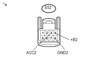
*a |
Front view of wire harness connector (to Stereo Component Tuner Assembly) |
| NG | .gif) |
GO TO STEP 4 |
|
.gif)
|
2. |
REPLACE NO. 1 NAVIGATION WIRE |
(a) Replace the No. 1 navigation wire with a new or known good one (See page
.gif) ).
).
(b) Clear the DTCs (See page ).
(c) Recheck for DTCs and check that no DTCs are output.
OK:
No DTCs are output.
| OK | |
END |
|
|
3. |
REPLACE STEREO COMPONENT TUNER ASSEMBLY |
(a) Replace the stereo component tuner assembly with a new or known good one
(See page ).
(b) Clear the DTCs (See page ).
(c) Recheck for DTCs and check that no DTCs are output.
OK:
No DTCs are output.
| OK | |
END |
| NG | |
REPLACE RADIO AND DISPLAY RECEIVER ASSEMBLY |
|
4. |
CHECK NO. 1 NAVIGATION WIRE |
(a) Disconnect the R27 radio and display receiver assembly connector.
(b) Disconnect the S52 stereo component tuner assembly connector.
(c) Measure the resistance according to the value(s) in the table below.
Standard Resistance:
|
Tester Connection |
Condition |
Specified Condition |
|---|---|---|
|
R27-4 (+B2) - S52-4 (+B2) |
Always |
Below 1 Ω |
|
R27-3 (ACC2) - S52-3 (ACC2) |
Always |
Below 1 Ω |
|
R27-8 (GND2) - S52-8 (GND2) |
Always |
Below 1 Ω |
|
R27-4 (+B2) - Body ground |
Always |
10 kΩ or higher |
|
R27-3 (ACC2) - Body ground |
Always |
10 kΩ or higher |
|
R27-8 (GND2) - Body ground |
Always |
10 kΩ or higher |
| OK | |
REPLACE RADIO AND DISPLAY RECEIVER ASSEMBLY |
| NG | |
REPLACE NO. 1 NAVIGATION WIRE |
 Lost Communication with Meter (B1324)
DESCRIPTION
This DTC is stored when a communication error occurs between the radio and display
receiver assembly and combination meter assembly.
DTC No.
DTC Detection Conditi ...
 HD Radio Tuner Malfunction (B1551,B158D,B15A0,B15B0,B15B3,B15B4,B15B7)
DESCRIPTION
These DTCs are stored when a malfunction occurs in the radio and display receiver
assembly.
DTC No.
DTC Detection Condition
Trouble Area
...
Other materials:
Components
COMPONENTS
ILLUSTRATION
*1
FRONT FENDER LINER
*2
FRONT NO.1 WHEEL OPENING EXTENSION PAD
*3
FOG LIGHT UNIT
-
-
...
Installation
INSTALLATION
PROCEDURE
1. INSPECT AND ADJUST BRAKE BOOSTER PUSH ROD
NOTICE:
The brake booster interior must not be a vacuum when adjusting the booster. Stop
the engine and depress the brake pedal several times until there is no vacuum in
the booster.
HINT:
Adjust the booster push rod when ...
Diagnosis System
DIAGNOSIS SYSTEM
1. DESCRIPTION
(a) Smart key system (for entry function) data and Diagnostic Trouble Codes (DTCs)
can be read through the vehicle Data Link Connector 3 (DLC3). In some cases, a malfunction
may be occurring in the smart key system. When the system seems to be malfunctioning,
...
