Toyota Tacoma (2015-2018) Service Manual: Inspection
INSPECTION
PROCEDURE
1. INSPECT FUEL DELIVERY PIPE SUB-ASSEMBLY LH (FUEL PRESSURE SENSOR)
NOTICE:
- Do not remove the fuel pressure sensor from the fuel delivery pipe sub-assembly LH.
- If a fuel pressure sensor is removed, replace the fuel delivery pipe sub-assembly LH with a new one.
(a) Remove the fuel delivery pipe sub-assembly LH (See page
.gif) ).
).
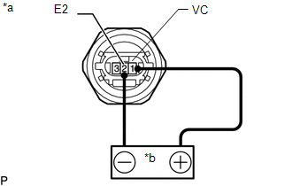
(b) Check the fuel pressure sensor output voltage.
|
(1) Apply 5 V between terminals 1 (VC) and 2 (E2). Text in Illustration
NOTICE:
HINT: If a stable power supply is not available, use 4 1.2 V nickel-metal hydride batteries or equivalent. |
|
|
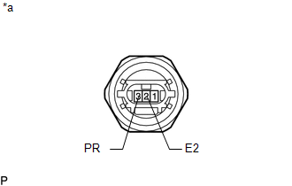
(2) Measure the voltage between terminals. Text in Illustration
Standard Voltage:
*: The output voltage changes depending on the voltage applied to the terminals. Output voltage = (0.08 x Voltage applied to terminals) to (0.12 x Voltage applied to terminals) If the result is not as specified, replace the fuel delivery pipe sub-assembly LH. |
|
(c) Install the fuel delivery pipe sub-assembly LH (See page
).
 Removal
REMOVAL
PROCEDURE
1. REMOVE FUEL DELIVERY PIPE ASSEMBLY LH (FUEL PRESSURE SENSOR)
(See page )
NOTICE:
Do not remove the fuel pressure sensor from the fuel delivery pipe sub-assembly
...
 Installation
INSTALLATION
CAUTION / NOTICE / HINT
HINT:
Perform "Inspection After Repairs" after replacing the fuel delivery pipe assembly
LH (fuel pressure sensor) (See page ).
PROCEDURE
1. INST ...
Other materials:
Diagnostic Trouble Code Chart
DIAGNOSTIC TROUBLE CODE CHART
Forward Recognition Camera System
DTC No.
Detection Item
Link
C1A0A
Front Radar Sensor Region Code Mismatch
C1A47
Steering Angle Sensor
...
Vacuum Pump
Components
COMPONENTS
ILLUSTRATION
Installation
INSTALLATION
PROCEDURE
1. INSTALL VACUUM PUMP ASSEMBLY
(a) Apply engine oil to the 2 O-rings on the vacuum pump assembly.
(b) Apply engine oil to the inner surface of the installation hole.
(c) Install the vacuum pump assembly so that th ...
Reassembly
REASSEMBLY
PROCEDURE
1. INSTALL GENERATOR DRIVE END FRAME BEARING
(a) Using SST and a press, press in a new generator drive end frame bearing.
SST: 09950-60010
09951-00470
SST: 09950-70010
09951-07100
(b) Fit the ta ...
