Toyota Tacoma (2015-2018) Service Manual: Installation
INSTALLATION
PROCEDURE
1. SET NO. 1 CYLINDER TO TDC/COMPRESSION
.gif)
2. INSTALL CAMSHAFT TIMING GEAR BOLT
NOTICE:
There are different types of camshaft timing gear bolts. Make sure to check the identification mark to determine the tightening torque.
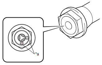
|
*a |
Identification Mark Stamp |
|
Item |
Identification Mark Stamp |
|
|---|---|---|
|
Intake Side |
Exhaust Side |
|
|
Type A |
A |
B |
|
Type B |
D |
G |
|
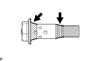
(a) Apply engine oil to the areas of the camshaft timing gear bolt shown in the illustration. |
|
(b) Temporarily install the camshaft timing gear bolt.
Torque:
10 N·m {102 kgf·cm, 7 ft·lbf}
HINT:
Make sure that the flange part of the camshaft timing gear bolt is directly contacting the camshaft timing gear assembly.
(c) Loosen the camshaft timing gear bolt 60 to 180°.
|
(d) Using SST, hold the crankshaft pulley assembly. SST: 09213-54015 91651-60855 SST: 09330-00021 |
|
.png)
(e) Tighten the camshaft timing gear bolt.
Torque:
for Type A :
120 N·m {1224 kgf·cm, 89 ft·lbf}
for Type B :
95 N·m {969 kgf·cm, 70 ft·lbf}
3. INSTALL CAMSHAFT TIMING OIL CONTROL SOLENOID ASSEMBLY
(See page )
4. INSTALL NO. 1 ENGINE UNDER COVER SUB-ASSEMBLY
Torque:
30 N·m {306 kgf·cm, 22 ft·lbf}
5. INSTALL NO. 2 ENGINE UNDER COVER SUB-ASSEMBLY (w/ Off Road Package)
Torque:
30 N·m {306 kgf·cm, 22 ft·lbf}
 Removal
REMOVAL
CAUTION / NOTICE / HINT
NOTICE:
If one of the camshaft timing gear bolts is already removed, do not remove any
other camshaft timing gear bolts.
PROCEDURE
1. REMOVE NO. 2 ENGINE UNDER C ...

Other materials:
System Description
SYSTEM DESCRIPTION
1. WIRELESS DOOR LOCK CONTROL SYSTEM
The wireless door lock control system functions to lock and unlock all the doors
from a distance. The system is controlled by a door control transmitter module set
sub-assembly which sends radio waves to the door control receiver. The mai ...
Fender Panel Mudguard
Components
COMPONENTS
ILLUSTRATION
ILLUSTRATION
Installation
INSTALLATION
CAUTION / NOTICE / HINT
HINT:
Use the same procedure for the RH side and LH side.
The following procedure is for the LH side.
PROCEDURE
1. INSTALL FRONT FENDER MUDGUARD
(a) Install the fron ...
Sun visors
Type A
Forward position: Flip down.
Side position: Flip down, unhook,
and swing to the side.
Type B
Forward position: Flip down.
Side position: Flip down, unhook,
and swing to the side.
Side extender: Place in side position,
then slide backwards. ...
