Toyota Tacoma (2015-2018) Service Manual: Installation
INSTALLATION
PROCEDURE
1. INSTALL LOWER NO. 1 INSTRUMENT PANEL AIRBAG ASSEMBLY
|
(a) Connect the airbag connector. NOTICE: When handling the airbag connector, take care not to damage the airbag wire harness. |
|
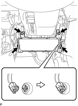
(b) Push in the airbag connector lock to install the airbag connector.
(c) Install the lower No. 1 instrument panel airbag assembly with the 4 bolts.
Torque:
10 N·m {102 kgf·cm, 7 ft·lbf}
2. INSTALL INSTRUMENT PANEL LOWER FINISH PANEL SUB-ASSEMBLY LH
.gif)
3. CONNECT HOOD LOCK CONTROL LEVER SUB-ASSEMBLY
4. INSTALL COWL SIDE TRIM BOARD LH
5. INSTALL FRONT DOOR SCUFF PLATE LH
6. CONNECT CABLE TO NEGATIVE BATTERY TERMINAL
Torque:
5.4 N·m {55 kgf·cm, 48 in·lbf}
NOTICE:
When disconnecting the cable, some systems need to be initialized after the cable is reconnected.
Click here
7. INSPECT SRS WARNING LIGHT
Click here
 Disposal
DISPOSAL
CAUTION / NOTICE / HINT
CAUTION:
Before performing pre-disposal deployment of any SRS part, review and closely
follow all applicable environmental and hazardous material regulations. Pre ...

Other materials:
Horn System
Parts Location
PARTS LOCATION
ILLUSTRATION
Precaution
PRECAUTION
1. IGNITION SWITCH EXPRESSIONS
(a) The type of ignition switch used on this model differs depending on the specifications
of the vehicle. The expressions listed in the table below are used in this section.
Exp ...
Differential Oil
Adjustment
ADJUSTMENT
PROCEDURE
1. INSPECT DIFFERENTIAL OIL
(a) Stop the vehicle on a level place.
(b) Remove the differential filler plug and gasket.
(c) Check that the oil level is within 5 mm (0 to 0.20 in.) of the bottom of
the filler plug opening.
NOTICE:
Excessively large ...
Problem Symptoms Table
PROBLEM SYMPTOMS TABLE
HINT:
Use the table below to help determine the cause of problem symptoms.
If multiple suspected areas are listed, the potential causes of the symptoms
are listed in order of probability in the "Suspected Area" column of the
table. Check each sy ...
