Toyota Tacoma (2015-2018) Service Manual: Amplifier Box Speaker Assembly
Components
COMPONENTS
ILLUSTRATION
ILLUSTRATION
Removal
REMOVAL
PROCEDURE
1. PRECAUTION
NOTICE:
After turning the ignition switch off, waiting time may be required before disconnecting the cable from the negative (-) battery terminal. Therefore, make sure to read the disconnecting the cable from the negative (-) battery terminal notices before proceeding with work.
Click here .gif)
2. DISCONNECT CABLE FROM NEGATIVE BATTERY TERMINAL
NOTICE:
When disconnecting the cable, some systems need to be initialized after the cable is reconnected.
Click here
3. REMOVE REAR SEATBACK ASSEMBLY RH
(See page )
4. REMOVE REAR SEATBACK ASSEMBLY LH
(See page )
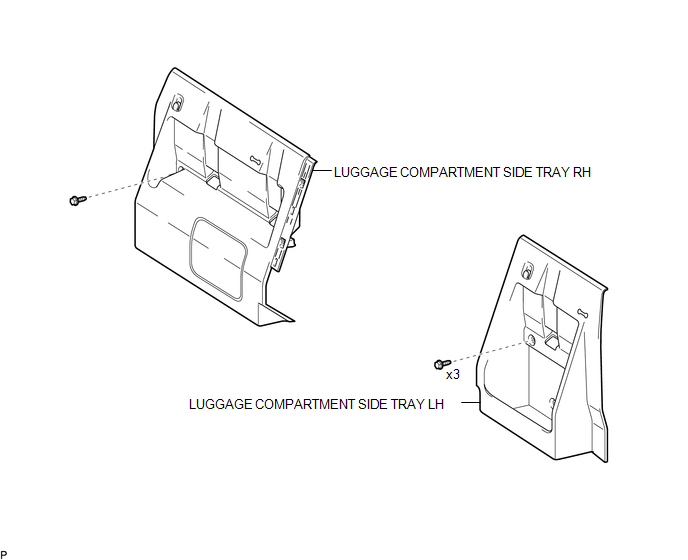
5. REMOVE LUGGAGE COMPARTMENT SIDE TRAY LH
(See page )
6. REMOVE LUGGAGE COMPARTMENT SIDE TRAY RH
(See page )
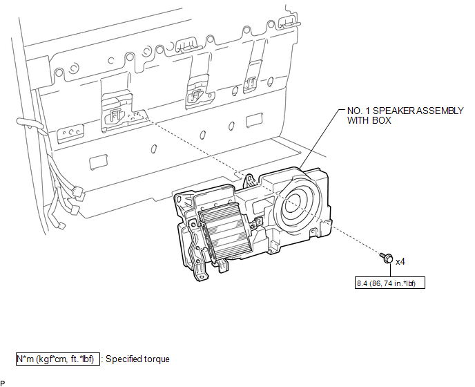
7. REMOVE NO. 1 SPEAKER ASSEMBLY WITH BOX
(a) Disconnect the 4 connectors.
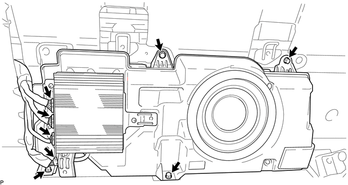
(b) Remove the 4 bolts and the No. 1 speaker assembly with box.
Installation
INSTALLATION
PROCEDURE
1. INSTALL NO. 1 SPEAKER ASSEMBLY WITH BOX
(a) Install the No. 1 speaker assembly with box with the 4 bolts.
Torque:
8.4 N·m {86 kgf·cm, 74 in·lbf}
(b) Connect the 4 connectors.
2. INSTALL LUGGAGE COMPARTMENT SIDE TRAY RH
(See page .gif) )
)
3. INSTALL LUGGAGE COMPARTMENT SIDE TRAY LH
(See page )
4. INSTALL REAR SEATBACK ASSEMBLY LH
(See page )
5. INSTALL REAR SEATBACK ASSEMBLY RH
(See page )
6. CONNECT CABLE TO NEGATIVE BATTERY TERMINAL
Torque:
5.4 N·m {55 kgf·cm, 48 in·lbf}
NOTICE:
When disconnecting the cable, some systems need to be initialized after the cable is reconnected.
Click here
 Audio / Video
...

Other materials:
Crankshaft Position Sensor "A" Signal Stuck in Range (P03352A,P033531)
DESCRIPTION
The crankshaft position sensor system consists of a crankshaft position sensor
plate and a pickup coil. The crankshaft position sensor plate has 34 teeth and is
installed to the crankshaft. The pickup coil is made of wound copper wire, an iron
core and a magnet. The crankshaft pos ...
Blind Spot Monitor Main Switch
Components
COMPONENTS
ILLUSTRATION
Removal
REMOVAL
PROCEDURE
1. REMOVE INSTRUMENT PANEL LOWER CENTER FINISH PANEL
(See page )
2. REMOVE BLIND SPOT MONITOR MAIN SWITCH (WARNING CANCELING SWITCH ASSEMBLY)
(a) Disengage the 2 claws to remove the blind spot monitor main switch ...
While Alarm is Armed, Engine Hood is opened but Alarm does not Sound
DESCRIPTION
A situation in which the alarm is armed but does not sound when the hood is opened
can be caused when the main body ECU (multiplex network body ECU) cannot detect
whether the hood courtesy switch is open or closed.
If the alarm does not sound, there may be a malfunction in the hood ...
