Toyota Tacoma (2015-2018) Service Manual: Components
COMPONENTS
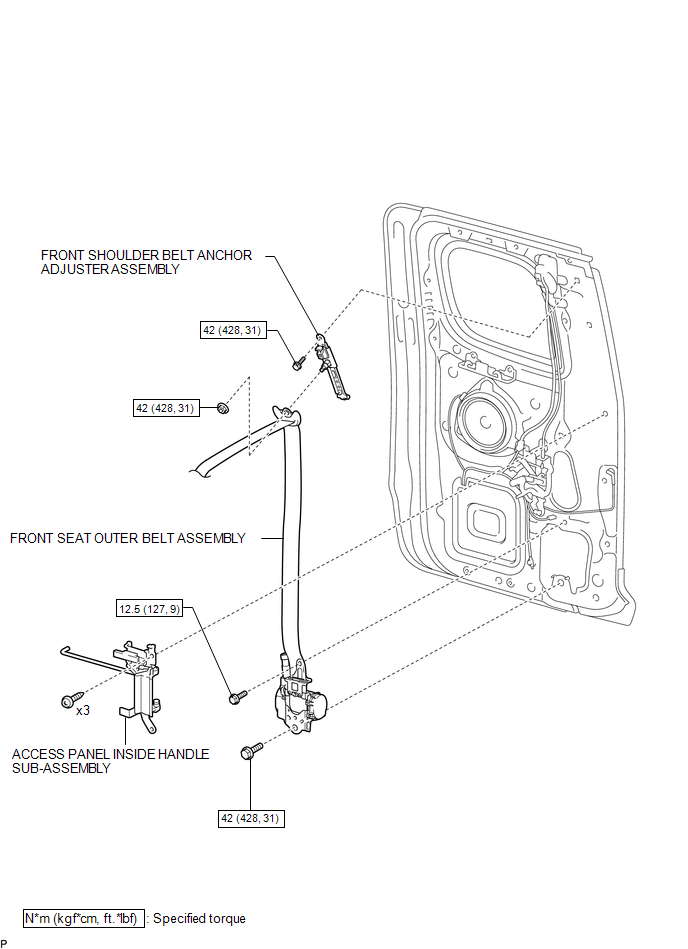
ILLUSTRATION

ILLUSTRATION

 Installation
INSTALLATION
CAUTION / NOTICE / HINT
HINT:
Use the same procedure for both the RH and LH sides.
The procedure described below is for the LH side.
PROCEDURE
1. INSTALL FRONT SHOU ...
Other materials:
Deck Light Relay
Inspection
INSPECTION
PROCEDURE
1. REMOVE DECK LIGHT RELAY
(a) Check the resistance.
(1) Measure the resistance according to the value(s) in the table below.
Standard:
Tester Connection
Condition
Specified Condition
...
Disassembly
DISASSEMBLY
PROCEDURE
1. REMOVE ROOM LIGHT BRACKET
(a) Disengage the guide to remove the room light bracket.
2. REMOVE SLIDING ROOF DRIVE GEAR SUB-ASSEMBLY
(a) Remove the 2 bolts and sliding roof drive gear sub-assembly.
...
Terminals Of Ecm
TERMINALS OF ECM
HINT:
The standard normal voltage between each pair of ECM terminals is shown in the
table below. The appropriate conditions for checking each pair of terminals are
also indicated. The result of checks should be compared with the standard normal
voltage for that pair of te ...
