Toyota Tacoma (2015-2018) Service Manual: High Pitched Horn
Components
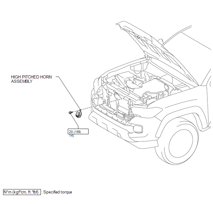
COMPONENTS
ILLUSTRATION
Removal
REMOVAL
PROCEDURE
1. REMOVE RADIATOR GRILLE
Click here .gif)
2. REMOVE HIGH PITCHED HORN ASSEMBLY
|
(a) Disconnect the connector. |
|
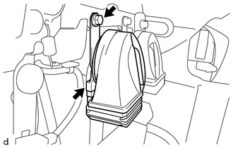
(b) Remove the bolt and high pitched horn assembly.
Inspection
INSPECTION
PROCEDURE
1. INSPECT HIGH PITCHED HORN ASSEMBLY
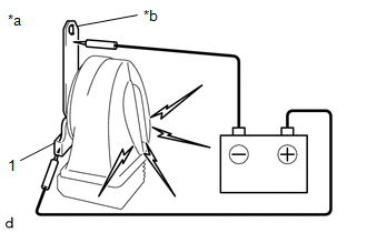
(a) Check the operation.
|
(1) Apply battery voltage to the terminal 1 and body ground, and check that the high pitched horn assembly sounds. Text in Illustration
OK:
If the result is not as specified, replace the high pitched horn assembly. |
|
Installation
INSTALLATION
PROCEDURE
1. INSTALL HIGH PITCHED HORN ASSEMBLY
(a) Install the high pitched horn assembly with the bolt.
Torque:
20 N·m {199 kgf·cm, 14 ft·lbf}
(b) Connect the connector.
2. INSTALL RADIATOR GRILLE
Click here .gif)
 Horn
Horn
...
 Horn Relay
On-vehicle Inspection
ON-VEHICLE INSPECTION
PROCEDURE
1. INSPECT HORN RELAY ASSEMBLY
(a) Check the resistance.
(1) Measure the resistance according to the value(s) in the table below ...
Other materials:
Short to +B in Buzzer (C1ABD,C1ABE)
DESCRIPTION
DTC C1ABD is stored when the blind spot monitor sensor RH detects a
+B short in rear cross traffic alert buzzer (blind spot monitor buzzer)
circuit.
DTC C1ABE is stored when the blind spot monitor sensor RH detects a
ground short or open in rear cross traffic aler ...
Lost Communication with ECM (C1437)
DESCRIPTION
The skid control ECU (master cylinder solenoid) receives signals from the ECM
via the CAN communication system.
DTC Code
DTC Detection Condition
Trouble Area
C1437
When the IG1 terminal voltage is 10 V or higher and the veh ...
CD cannot be Inserted / Played or CD is Ejected Right After Insertion
PROCEDURE
1.
CHECK IF A PROPER CD IS INSERTED
(a) Make sure that the CD is an audio CD or a CD with an MP3, WMA or AAC file,
and that it is not deformed, flawed, stained, deteriorated or otherwise defective.
OK:
CD is normal.
HINT:
Translucent or uniq ...
