Toyota Tacoma (2015-2018) Service Manual: Installation
INSTALLATION
PROCEDURE
1. INSTALL CLUTCH PEDAL NO.1 CUSHION
(a) Install the clutch pedal No. 1 cushion to the clutch pedal sub-assembly.
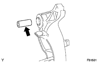
2. INSTALL CLUTCH PEDAL SHAFT COLLAR
(a) Apply MP grease to the clutch pedal shaft collar.
 Text in Illustration
.png) |
MP grease |
(b) Install the clutch pedal shaft collar to the clutch pedal sub-assembly.
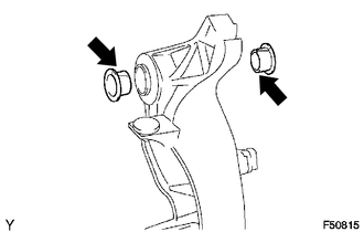
3. INSTALL CLUTCH PEDAL BUSH
(a) Apply MP grease to 2 new bushes.
 Text in Illustration
|
|
MP grease |
(b) Install the 2 bushes to the clutch pedal sub-assembly.
4. INSTALL CLUTCH PEDAL PAD
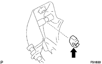
5. INSTALL CLUTCH PEDAL SPRING HOLDER
(a) Apply MP grease to the contact surface of the clutch pedal spring holder and clutch pedal support.
 Text in Illustration
|
|
MP grease |
(b) Install the clutch pedal spring holder.
6. INSTALL CLUTCH PEDAL SUB-ASSEMBLY
(a) Install the clutch pedal sub-assembly to the clutch pedal support with the bolt and nut.
Torque:
34 N·m {350 kgf·cm, 25 ft·lbf}
HINT:
Install the bolt from the left side of the vehicle.
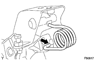
7. INSTALL TURN OVER SPRING SEAT COMPRESSION SPRING
(a) Apply MP grease to the contact surfaces of the clutch pedal sub-assembly and the compression spring.
 Text in Illustration
|
|
MP grease |
(b) Install the compression spring to the clutch pedal sub-assembly and the clutch pedal spring holder.
8. INSTALL CLUTCH MASTER CYLINDER ASSEMBLY
(See page .gif) )
)
 Adjustment
ADJUSTMENT
PROCEDURE
1. INSPECT AND ADJUST CLUTCH PEDAL
(a) Fold back the floor carpet.
(b) Check that the pedal height is correct.
Text in Illustration
*a
...
 Clutch Pedal Switch
On-vehicle Inspection
ON-VEHICLE INSPECTION
PROCEDURE
1. CHECK CLUTCH START SYSTEM
(a) Check that the engine does not start when the clutch pedal is released.
(b) Check that the engine starts ...
Other materials:
XM Tuner Antenna Disconnected (B15FE,B15FF)
DESCRIPTION
These DTCs are stored when a malfunction occurs in the antenna assembly with
holder which is connected to the radio and display receiver assembly.
DTC No.
DTC Detection Condition
Trouble Area
B15FE
The antenna assembly with ...
Steering Angle Sensor Internal Circuit (C1433)
DESCRIPTION
Steering angle sensor (spiral cable with sensor sub-assembly) signals are sent
to the skid control ECU (master cylinder solenoid) via the CAN communication system.
When there is a malfunction in the CAN communication system, it is detected by the
steering angle sensor (spiral cabl ...
General maintenance
Listed below are the general maintenance items that should be performed at
the intervals specified in the “Scheduled Maintenance Guide” or “Owner’s Manual
Supplement”. It is recommended that any problem you notice should be brought to
the attention of your Toyota dealer or qualified ...
