Toyota Tacoma (2015-2018) Service Manual: Clutch Pedal Switch
On-vehicle Inspection
ON-VEHICLE INSPECTION
PROCEDURE
1. CHECK CLUTCH START SYSTEM
(a) Check that the engine does not start when the clutch pedal is released.
(b) Check that the engine starts when the clutch pedal is fully depressed.
If necessary, replace the clutch start switch assembly.
Inspection
INSPECTION
PROCEDURE
1. INSPECT CLUTCH START SWITCH ASSEMBLY
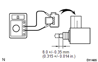
(a) Measure the resistance between the terminals when the switch is ON and OFF.
|
Switch Position |
Specified Condition |
|---|---|
|
ON (pushed) |
Below 1 Ω |
|
OFF (free) |
10 kΩ or higher |
Removal
REMOVAL
PROCEDURE
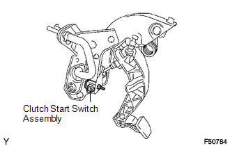
1. REMOVE CLUTCH START SWITCH ASSEMBLY
(a) Disconnect the clutch start switch assembly connector.
(b) Remove the nut and clutch start switch assembly from the clutch pedal support.
Installation
INSTALLATION
PROCEDURE
1. INSTALL CLUTCH START SWITCH ASSEMBLY
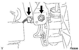
(a) Install the clutch start switch assembly with the nut.
Torque:
16 N·m {160 kgf·cm, 12 ft·lbf}
(b) Connect the clutch start switch assembly connector.
2. INSPECT CLUTCH START SWITCH ASSEMBLY
.gif)
 Installation
INSTALLATION
PROCEDURE
1. INSTALL CLUTCH PEDAL NO.1 CUSHION
(a) Install the clutch pedal No. 1 cushion to the clutch pedal sub-assembly.
2. INSTALL CLUTCH PEDAL SHAFT COLLAR
(a) Apply MP grease t ...
 Clutch Release Cylinder(for R156f)
Components
COMPONENTS
ILLUSTRATION
Removal
REMOVAL
PROCEDURE
1. DRAIN CLUTCH FLUID
2. REMOVE FRONT PROPELLER SHAFT ASSEMBLY
(See page )
3. DISCONNECT CLUTCH RELEASE CYLINDER TO FLEXIBL ...
Other materials:
Brake Warning Light does not Come ON
DESCRIPTION
The skid control ECU (brake actuator assembly) is connected to the combination
meter assembly via CAN communication.
WIRING DIAGRAM
Refer to Brake Warning Light Remains ON (See page
).
CAUTION / NOTICE / HINT
NOTICE:
When replacing the skid control ECU (brake actuator assembly) ...
Lost Communication with Front Camera Module (U023A)
DESCRIPTION
These DTCs are stored when the CAN communication system is malfunctioning.
DTC No.
DTC Detecting Condition
Trouble Area
U023A
Lost Communication With Image Processing Module"A"
The main body ECU ...
Disassembly
DISASSEMBLY
PROCEDURE
1. INSPECT PROPELLER SHAFT UNIVERSAL JOINT SPIDER BEARING
(a) Check the spider bearings for wear and damage.
(b) Check each spider bearings axial play by turning the yoke while holding the
shaft tightly.
Maximum bearing axial play:
0 to 0.05 mm (0 to 0.00197 in.)
If t ...
