Toyota Tacoma (2015-2018) Service Manual: Installation
INSTALLATION
PROCEDURE
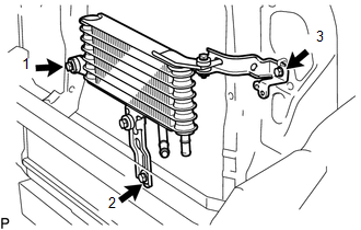
1. INSTALL OIL COOLER ASSEMBLY (w/ Air Cooled Transmission Oil Cooler)
(a) Install the 2 oil cooler brackets to the oil cooler assembly with the 2 bolts.
Torque:
5.5 N·m {56 kgf·cm, 49 in·lbf}
|
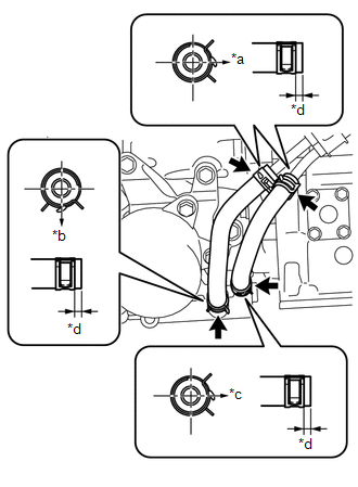
(b) Install the oil cooler assembly to the vehicle body with the 3 bolts in the order shown in the illustration. Torque: 5.5 N·m {56 kgf·cm, 49 in·lbf} |
|
2. INSTALL NO. 1 OIL COOLER TUBE SUB-ASSEMBLY (w/ Air Cooled Transmission Oil Cooler)
(a) Install the No.1 oil cooler tube sub-assembly to the oil cooler bracket with the bolt.
Torque:
5.5 N·m {56 kgf·cm, 49 in·lbf}
3. INSTALL NO. 6 OIL COOLER INLET HOSE AND NO. 6 OIL COOLER OUTLET HOSE (w/ Air Cooled Transmission Oil Cooler)
NOTICE:
- When connecting the hoses to the tube, support the tube by hand and be careful to prevent the tube from being deformed.
- Make sure to install the clips so that the spool fitting is not overlapped.
(a) Install the No. 6 oil cooler inlet hose and No. 6 oil cooler outlet hose to the oil cooler assembly, and slide the 2 clips to secure them.
NOTICE:
Make sure to install any hose clips without a specific installation direction in a direction that does not interfere with other parts.
(b) Connect the No. 6 oil cooler inlet hose and No. 6 oil cooler outlet hose to the No.1 oil cooler tube sub-assembly, and slide the 2 clips to secure them.
NOTICE:
Make sure to install any hose clips without a specific installation direction in a direction that does not interfere with other parts.
4. INSTALL OIL COOLER TUBE
(a) Install the oil cooler tube to the vehicle body with the 2 bolts.
Torque:
28 N·m {286 kgf·cm, 21 ft·lbf}
5. INSTALL NO. 5 OIL COOLER OUTLET HOSE (w/ Air Cooled Transmission Oil Cooler)
NOTICE:
- When connecting the hoses to the tube, support the tube by hand and be careful to prevent the tube from being deformed.
- Make sure to install the clips so that the spool fitting is not overlapped.
(a) Install the No. 5 oil cooler outlet hose to the No.1 oil cooler tube sub-assembly, and slide the clip to secure it.
NOTICE:
Make sure to install any hose clips without a specific installation direction in a direction that does not interfere with other parts.
(b) Connect the No. 5 oil cooler outlet hose to the radiator assembly, and slide the clip to secure it.
NOTICE:
Make sure to install any hose clips without a specific installation direction in a direction that does not interfere with other parts.
6. INSTALL NO. 4 OIL COOLER INLET HOSE AND NO. 4 OIL COOLER OUTLET HOSE
NOTICE:
- When connecting the hoses to the tube, support the tube by hand and be careful to prevent the tube from being deformed.
- Make sure to install the clips so that the spool fitting is not overlapped.
(a) w/o Air Cooled Transmission Oil Cooler:
(1) Install the No. 4 oil cooler inlet hose and No. 4 oil cooler outlet hose to the radiator assembly, and slide the 2 clips to secure them.
NOTICE:
Make sure to install any hose clips without a specific installation direction in a direction that does not interfere with other parts.
(b) w/ Air Cooled Transmission Oil Cooler:
(1) Install the No. 4 oil cooler inlet hose and No. 4 oil cooler outlet hose to the radiator assembly and No.1 oil cooler tube sub-assembly, and slide the 2 clips to secure them.
NOTICE:
Make sure to install any hose clips without a specific installation direction in a direction that does not interfere with other parts.
(c) Connect the No. 4 oil cooler inlet hose and No. 4 oil cooler outlet hose to the oil cooler tube, and slide the 2 clips to secure them.
NOTICE:
Make sure to install any hose clips without a specific installation direction in a direction that does not interfere with other parts.
(d) Then pass the No. 4 oil cooler inlet hose and No. 4 oil cooler outlet hose through the clamp and close the clamp.
7. INSTALL NO. 1 OIL COOLER INLET TUBE AND NO. 1 OIL COOLER OUTLET TUBE
(a) Install the 2 oil cooler tube clamps to the automatic transmission assembly and engine assembly with the 2 bolts.
Torque:
14 N·m {143 kgf·cm, 10 ft·lbf}
(b) Install the No. 1 oil cooler inlet tube, No. 1 oil cooler outlet tube and 2 flexible hose clamps to the 2 oil cooler tube clamps with the 2 bolts.
Torque:
5.5 N·m {56 kgf·cm, 49 in·lbf}
8. INSTALL NO. 3 OIL COOLER INLET HOSE AND NO. 3 OIL COOLER OUTLET HOSE
NOTICE:
- When connecting the hoses to the tube, support the tube by hand and be careful to prevent the tube from being deformed.
- Make sure to install the clips so that the spool fitting is not overlapped.
(a) Install the No. 3 oil cooler inlet hose and No. 3 oil cooler outlet hose to the No. 1 oil cooler inlet tube and No. 1 oil cooler outlet tube, and slide the 2 clips to secure them.
NOTICE:
Make sure to install any hose clips without a specific installation direction in a direction that does not interfere with other parts.
(b) Connect the No. 3 oil cooler inlet hose and No. 3 oil cooler outlet hose to the oil cooler tube, and slide the 2 clips to secure them.
NOTICE:
Make sure to install any hose clips without a specific installation direction in a direction that does not interfere with other parts.
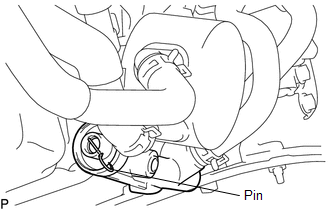
9. INSTALL TRANSMISSION OIL COOLER ASSEMBLY
NOTICE:
- When the transmission oil thermostat is replaced with a new one, pull
out the pin from the new transmission oil thermostat.
- Make sure to install the clips so that the spool fitting is not overlapped.
(a) Coat 2 new O-rings with ATF, and install them to the transmission oil cooler assembly.
(b) Align the transmission oil cooler assembly with the transmission oil thermostat and assemble them with the 3 bolts.
Torque:
14 N·m {143 kgf·cm, 10 ft·lbf}
|
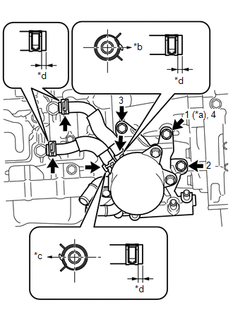
(c) Install the transmission oil cooler assembly with transmission oil thermostat to the automatic transmission assembly with the 3 bolts in the order shown in the illustration. Text in Illustration
Torque: 21 N·m {214 kgf·cm, 15 ft·lbf} |
|
(d) Install the No. 1 oil cooler inlet hose and No. 1 oil cooler outlet hose to the transmission oil thermostat, and slide the 2 clips to secure them.
NOTICE:
Make sure to install any hose clips without a specific installation direction in a direction that does not interfere with other parts.
(e) Connect the No. 1 oil cooler inlet hose and No. 1 oil cooler outlet hose to the automatic transmission assembly, and slide the 2 clips to secure them.
NOTICE:
Make sure to install any hose clips without a specific installation direction in a direction that does not interfere with other parts.
|
(f) Connect the 2 water by-pass hoses to the transmission oil cooler assembly, and slide the 2 clips to secure them. Text in Illustration
NOTICE: Make sure to install any hose clips without a specific installation direction in a direction that does not interfere with other parts. |
|
10. INSTALL NO. 2 OIL COOLER INLET HOSE AND NO. 2 OIL COOLER OUTLET HOSE
NOTICE:
- When connecting the hoses to the tube, support the tube by hand and be careful to prevent the tube from being deformed.
- Make sure to install the clips so that the spool fitting is not overlapped.
|
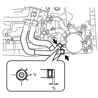
(a) Install the No. 2 oil cooler inlet hose and No. 2 oil cooler outlet hose to the transmission oil thermostat, and slide the 2 clips to secure them. Text in Illustration
NOTICE: Make sure to install any hose clips without a specific installation direction in a direction that does not interfere with other parts. |
|
(b) Connect the No. 2 oil cooler inlet hose and No. 2 oil cooler outlet hose to the No. 1 oil cooler inlet tube and No. 1 oil cooler outlet tube, and slide the 2 clips to secure them.
NOTICE:
Make sure to install any hose clips without a specific installation direction in a direction that does not interfere with other parts.
11. INSTALL EXHAUST MANIFOLD SUB-ASSEMBLY RH
(See page .gif)
12. INSTALL RADIATOR GRILLE
(See page )
13. ADD ENGINE COOLANT
14. ADD AUTOMATIC TRANSMISSION FLUID
(See page )
15. INSPECT FOR COOLANT LEAK
16. INSPECT FOR AUTOMATIC TRANSMISSION FLUID LEAK
17. INSTALL NO. 1 ENGINE UNDER COVER SUB-ASSEMBLY
Torque:
30 N·m {306 kgf·cm, 22 ft·lbf}
18. INSTALL NO. 2 ENGINE UNDER COVER SUB-ASSEMBLY (w/ Off Road Package)
Torque:
30 N·m {306 kgf·cm, 22 ft·lbf}
 Removal
REMOVAL
PROCEDURE
1. REMOVE NO. 2 ENGINE UNDER COVER SUB-ASSEMBLY (w/ Off Road Package)
2. REMOVE NO. 1 ENGINE UNDER COVER SUB-ASSEMBLY
3. DRAIN ENGINE COOLANT
4. REMOVE RADIATOR GRILLE
(See ...

Other materials:
Horn Relay
On-vehicle Inspection
ON-VEHICLE INSPECTION
PROCEDURE
1. INSPECT HORN RELAY ASSEMBLY
(a) Check the resistance.
(1) Measure the resistance according to the value(s) in the table below.
Standard Resistance:
Tester Connection
Connection
...
How To Proceed With Troubleshooting
CAUTION / NOTICE / HINT
HINT:
Use the following procedure to troubleshoot the intuitive parking assist
system.
*: Use the Techstream.
PROCEDURE
1.
VEHICLE BROUGHT TO WORKSHOP
NEXT
...
Four Wheel Drive (4WD) Range Signal Circuit Range / Performance (P279E)
DESCRIPTION
When the transfer position switch is switched, the 2-4 terminal and LO terminal
change to one of the following ON/OFF combinations listed in the table below.
Terminal
2WD
Between 2WD and H4
H4
Between H4 and L4
L4
...
