Toyota Tacoma (2015-2018) Service Manual: Installation
INSTALLATION
PROCEDURE
1. INSTALL ENGINE COOLANT TEMPERATURE SENSOR
.gif)
2. INSTALL ENGINE OIL PRESSURE SWITCH ASSEMBLY
3. INSTALL IGNITION COIL ASSEMBLY
4. INSTALL FUEL INJECTOR SEAL
5. INSTALL FUEL INJECTOR ASSEMBLY
6. INSTALL FUEL DELIVERY PIPE RH
7. INSTALL FUEL DELIVERY PIPE ASSEMBLY LH (FUEL PRESSURE SENSOR)
8. INSTALL NO. 2 FUEL PIPE SUB-ASSEMBLY
9. SET FUEL PUMP ASSEMBLY (for High Pressure)
10. TEMPORARILY INSTALL NO. 1 FUEL PIPE SUB-ASSEMBLY
11. INSTALL FUEL PUMP ASSEMBLY (for High Pressure)
12. INSTALL NO. 1 FUEL PIPE SUB-ASSEMBLY
13. INSTALL FUEL TUBE SUB-ASSEMBLY
14. INSTALL WIRE HARNESS CLAMP BRACKET
15. INSTALL INTAKE MANIFOLD
16. INSTALL FUEL DELIVERY PIPE SUB-ASSEMBLY
17. INSTALL VACUUM PUMP ASSEMBLY (for Vacuum Brake Booster)
18. INSTALL VACUUM PUMP HOLE COVER BRACKET (for Hydraulic Brake Booster)
(a) Install a new O-ring.
(b) Apply engine oil to the O-ring.
(c) Install the vacuum pump hole cover bracket with the 2 bolts.
Torque:
21 N·m {214 kgf·cm, 15 ft·lbf}
NOTICE:
- Be careful not to pinch the O-ring.
- After installation, check that there are no gaps between the matching surfaces and that the vacuum pump hole cover bracket is no installed at an angle.
19. CONNECT NO. 4 WATER BY-PASS HOSE (for Automatic Transmission)
(a) Connect the No. 4 water by-pass hose and slide the hose clip to secure it.
20. INSTALL NO. 2 WATER BY-PASS PIPE (for Automatic Transmission)
(a) Install the No. 2 water by-pass pipe with the 2 bolts.
Torque:
10 N·m {102 kgf·cm, 7 ft·lbf}
(b) Connect the No. 10 water by-pass hose and slide the hose clip to secure it.
21. INSTALL NO. 2 WATER BY-PASS PIPE (for Manual Transmission)
(a) Install the No. 2 water by-pass pipe with the 2 bolts.
Torque:
10 N·m {102 kgf·cm, 7 ft·lbf}
(b) Connect the No. 10 water by-pass hose and slide the 2 hose clips to secure it.
22. INSTALL WATER HOSE SUB-ASSEMBLY
(a) Install the water hose sub-assembly and slide the 2 hose clips to secure it.
23. INSTALL NO. 1 WATER BY-PASS PIPE (w/ Oil Cooler)
|
(a) Install the No. 1 water by-pass pipe with the 3 bolts and nut as shown in the illustration. Text in Illustration
Torque: 10 N·m {102 kgf·cm, 7 ft·lbf} |
|
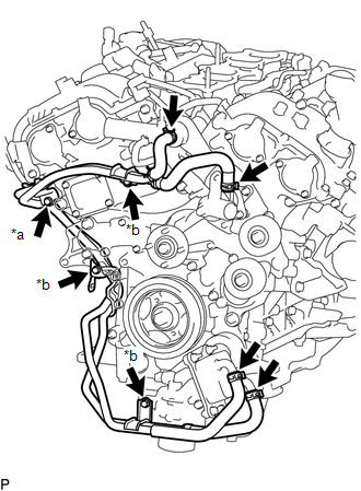
(b) Connect the 4 hoses and slide the 4 hose clips to secure it.
24. INSTALL NO. 4 WATER BY-PASS HOSE
(a) Install the No. 4 water by-pass hose and slide the hose clip to secure it.
25. INSTALL NO. 3 WATER BY-PASS HOSE
(a) Install the No. 3 water by-pass hose and slide the 2 hose clips to secure it.
26. INSTALL NO. 2 WATER BY-PASS HOSE
(a) Install the No. 2 water by-pass hose and slide the 2 hose clips to secure it.
27. INSTALL WATER BY-PASS HOSE
(a) Install the water by-pass hose and slide the 2 hose clips to secure it.
28. INSTALL NO. 5 WATER BY-PASS HOSE
(a) Install the No. 5 water by-pass hose and slide the hose clip to secure it.
29. INSTALL V-RIBBED BELT TENSIONER ASSEMBLY
(a) Install the V-ribbed belt tensioner assembly with the 2 bolts.
Torque:
43 N·m {438 kgf·cm, 32 ft·lbf}
30. INSTALL NO. 2 IDLER PULLEY SUB-ASSEMBLY
(a) Install the 2 No. 2 idler pulley sub-assemblies with the 2 bolts.
Torque:
43 N·m {438 kgf·cm, 32 ft·lbf}
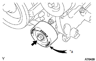
31. INSTALL NO. 1 IDLER PULLEY SUB-ASSEMBLY
|
(a) Install the No. 1 idler pulley sub-assembly with the bolt. Text in Illustration
Torque: 54 N·m {551 kgf·cm, 40 ft·lbf} HINT: "DOUBLE" is marked on the idler pulley to distinguish it from the No. 2 idler pulley. |
|
32. INSTALL NO. 1 COMPRESSOR MOUNTING BRACKET
(a) Install the No. 1 compressor mounting bracket with the 2 bolts.
Torque:
43 N·m {438 kgf·cm, 32 ft·lbf}
33. INSTALL FRONT NO. 1 ENGINE MOUNTING BRACKET LH
(a) Install the front No. 1 engine mounting bracket LH with the 3 bolts.
Torque:
43 N·m {438 kgf·cm, 32 ft·lbf}
34. INSTALL FRONT NO. 1 ENGINE MOUNTING BRACKET RH
(a) Install the front No. 1 engine mounting bracket RH with the 4 bolts.
Torque:
43 N·m {438 kgf·cm, 32 ft·lbf}
35. INSTALL OIL LEVEL DIPSTICK GUIDE
(a) Apply a light coat of the engine oil to a new O-ring.
(b) Install the O-ring.
NOTICE:
During installation, be careful not to damage the O-ring.
(c) Install the oil level dipstick guide with the bolt.
Torque:
10 N·m {102 kgf·cm, 7 ft·lbf}
NOTICE:
Make sure that the O-ring is not damaged or does not jump out of position during installation.
(d) Connect the clamp.
36. INSTALL OIL LEVEL DIPSTICK SUB-ASSEMBLY
(a) Install the oil level dipstick sub-assembly.
 Precaution
PRECAUTION
HINT:
Any digits beyond the 0.01 mm (1/1000 in.) place for standard, minimum
and maximum values should be used as a reference only.
When both standard and maximum or minim ...
 Front Crankshaft Oil Seal
Components
COMPONENTS
ILLUSTRATION
Installation
INSTALLATION
PROCEDURE
1. INSTALL TIMING GEAR CASE OR TIMING CHAIN CASE OIL SEAL
(a) Apply MP grease to the lip of a new timing gear case o ...
Other materials:
Removal
REMOVAL
PROCEDURE
1. REMOVE SHIFT LEVER KNOB SUB-ASSEMBLY (for Automatic Transmission)
(a) Using a molding remover A, disengage the 2 claws to separate the
shifting hole cover sub-assembly.
(b) Rotate the shift lever knob sub-as ...
Air conditioning system
Adjusting the settings
■ Adjusting the temperature setting
Turn the temperature control dial clockwise (warm) or counterclockwise (cool).
If is not pressed, the system will
blow ambient temperature air or heated air.
For quick cooling, turn the temperature control dial to the MAX A/C ...
Microphone Circuit between Microphone and Radio Receiver
DESCRIPTION
The navigation receiver assembly and telephone microphone assembly are connected
to each other using the microphone connection detection signal lines.
Using this circuit, the navigation receiver assembly sends power to the telephone
microphone assembly and the telephone microphone ...
