Toyota Tacoma (2015-2018) Service Manual: Inspection
INSPECTION
PROCEDURE
1. INSPECT TIE ROD END SUB-ASSEMBLY
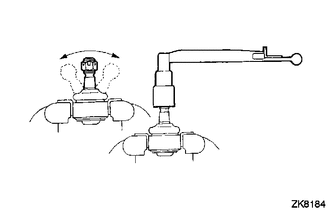
(a) Flip the ball joint stud back and forth 5 times as shown in the illustration before installing the nut.
(b) Using a torque wrench, turn the nut continuously at a rate of 2 to 4 seconds per turn and check the torque reading on the 5th turn.
Torque:
0.49-3.43 N·m {5.0-35.0 kgf·cm, 4.34-30.36 in·lbf}
2. INSPECT POWER STEERING RACK
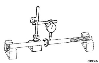
(a) Using a dial indicator, check the power steering rack for runout, teeth wear and damage.
Maximum runout:
0.3 mm (0.012 in.)
If necessary, replace the power steering link assembly.
(b) Check the back surface for wear and damage.
If necessary, replace the power steering link assembly.
 Disassembly
DISASSEMBLY
PROCEDURE
1. REMOVE STEERING GEAR OUTLET RETURN TUBE
(a) Using a union nut wrench, remove the steering gear outlet return tube.
2. REMOVE STEERING TURN PRESSURE TUBE
(a) Using a u ...
 Installation
INSTALLATION
PROCEDURE
1. INSTALL POWER STEERING LINK
(a) Insert the power steering link into the vehicle in the order shown in the
illustration.
Install in this Direction ...
Other materials:
Headlight Dimmer Relay
Inspection
INSPECTION
PROCEDURE
1. INSPECT HEADLIGHT DIMMER RELAY
(a) Check the resistance.
(1) Measure the resistance according to the value(s) in the table below.
Standard:
Tester Connection
Condition
Specified Condition
...
Rear Differential Lock Position SW Stuck ON (P17BC)
DESCRIPTION
This DTC is output when an ON malfunction of the differential lock indicator
switch is detected.
DTC No.
Detection Item
DTC Detection Condition
Trouble Area
P17BC
Rear Differential Lock Position SW Stuck ON
...
Removal
REMOVAL
PROCEDURE
1. REMOVE NO. 2 ENGINE UNDER COVER SUB-ASSEMBLY (w/ Off Road Package)
2. REMOVE NO. 1 ENGINE UNDER COVER SUB-ASSEMBLY
3. DRAIN ENGINE COOLANT
4. REMOVE RADIATOR GRILLE
(See page )
5. REMOVE V-BANK COVER SUB-ASSEMBLY
6. REMOVE RADIATOR SUPPORT TO FRAME SEAL
7. R ...
