Toyota Tacoma (2015-2018) Service Manual: Components
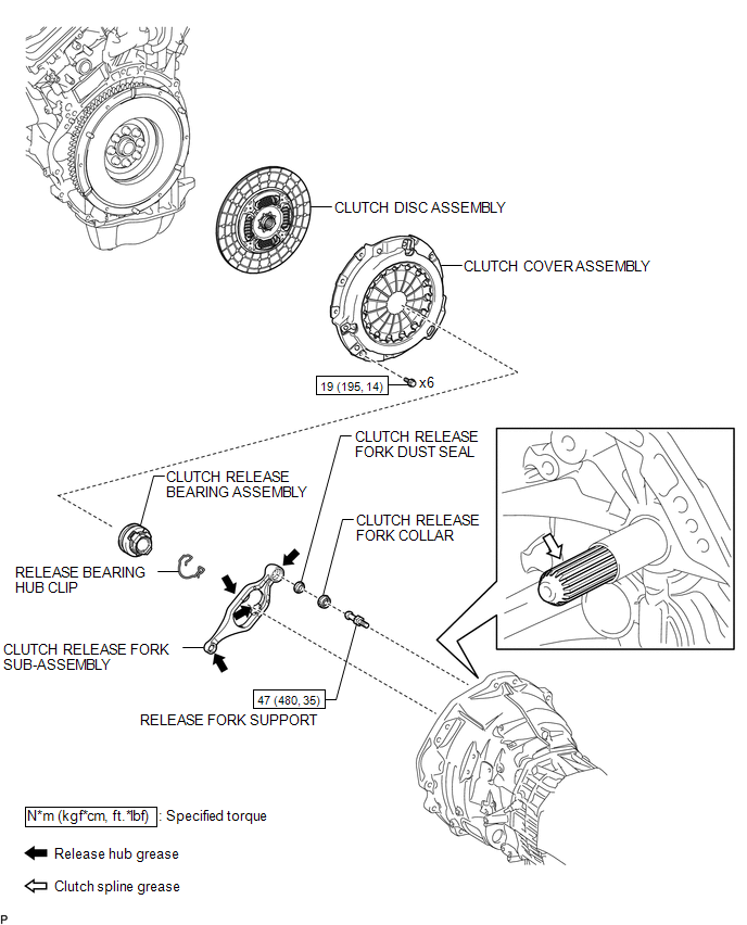
COMPONENTS
ILLUSTRATION

 Inspection
INSPECTION
PROCEDURE
1. INSPECT CLUTCH DISC ASSEMBLY
NOTICE:
When replacing the clutch disc assembly, make sure to perform an inspection of
the flywheel sub-assembly and clutch cover assembly.
...
Other materials:
Replacement
REPLACEMENT
PROCEDURE
1. REPLACE INTAKE VALVE GUIDE BUSH
(a) Heat the cylinder head to 80 to 100°C (176 to 212°F).
(b) Place the cylinder head on wooden blocks.
(c) Using SST and a hammer, tap out the intake valve guide bushes.
SST: 09201-10000
09201-01050
SST: 09950-70010 ...
Lock Switch Circuit
WIRING DIAGRAM
PROCEDURE
1.
CHECK REAR DIFFERENTIAL LOCK INDICATOR LIGHT
(a) Turn the ignition switch to ON.
(b) for 4WD:
Finish switching to L4.
(c) Check the rear differential lock indicator light.
(d) Press the differential lock switch.
(e) After 60 secon ...
Stereo Component Amplifier
Components
COMPONENTS
ILLUSTRATION
ILLUSTRATION
Removal
REMOVAL
PROCEDURE
1. PRECAUTION
NOTICE:
After turning the ignition switch off, waiting time may be required before disconnecting
the cable from the negative (-) battery terminal. Therefore, make sure to read the
disconnecti ...
