Components
COMPONENTS
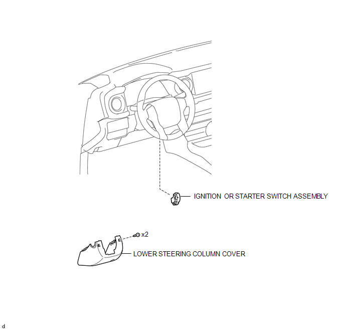
ILLUSTRATION
Removal
REMOVAL
PROCEDURE
1. REMOVE LOWER STEERING COLUMN COVER
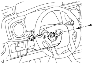
(a) Remove the 2 screws.
(b) Disengage the 2 claws and remove the lower steering column cover.
2. REMOVE IGNITION OR STARTER SWITCH ASSEMBLY
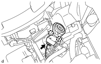
(a) Disconnect the connector.
(b) Disengage the 2 claws and remove the ignition or starter switch assembly.
Inspection
INSPECTION
PROCEDURE
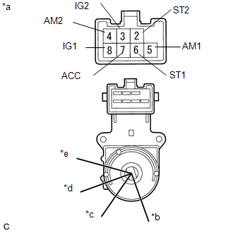
1. INSPECT IGNITION OR STARTER SWITCH ASSEMBLY
|
(a) Check the resistance. Text in Illustration
(1) Measure the resistance according to the value(s) in the table below. Standard Resistance:
If the result is not as specified, replace the ignition or starter switch assembly. |
|
Installation
INSTALLATION
PROCEDURE
1. INSTALL IGNITION OR STARTER SWITCH ASSEMBLY
(a) Engage the 2 claws and install the ignition or starter switch assembly.
(b) Connect the connector.
2. INSTALL LOWER STEERING COLUMN COVER
(a) Engage the 2 claws and install the lower steering column cover.
(b) Install the 2 screws.
HINT:
Turn the steering wheel to the right and left as necessary to install the 2 screws.