Toyota Tacoma (2015-2018) Service Manual: High Power Supply Voltage Malfunction (C1417)
DESCRIPTION
If a malfunction is detected in the power supply circuit, the skid control ECU (brake actuator assembly) stores this DTC and the fail-safe function prohibits ABS operation.
This DTC is stored when the +BS terminal voltage deviates from the DTC detection condition due to a malfunction in the power supply or charging circuit such as the battery or generator circuit, etc.
The DTC is canceled when the +BS terminal voltage returns to normal.
|
DTC No. |
Detection Item |
DTC Detection Condition |
Trouble Area |
|---|---|---|---|
|
C1417 |
High Power Supply Voltage Malfunction |
Either of the following is detected:
|
|
HINT:
DTC will be output when conditions for either of the patterns in the table above are met.
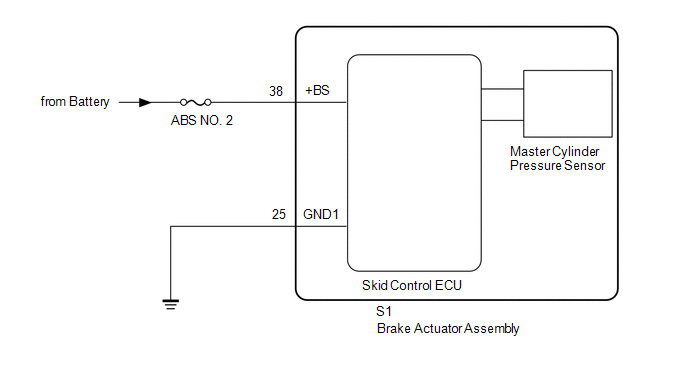
WIRING DIAGRAM
CAUTION / NOTICE / HINT
NOTICE:
- When replacing the skid control ECU (brake actuator assembly), perform
zero point calibration and store system information (See page
.gif) ).
).
- Inspect the fuses for circuits related to this system before performing the following inspection procedure.
PROCEDURE
|
1. |
INSPECT BATTERY |
(a) Check the battery voltage.
Standard voltage:
11 to 14 V
| NG | .gif) |
CHECK OR REPLACE CHARGING SYSTEM OR BATTERY |
|
.gif)
|
2. |
CHECK TERMINAL VOLTAGE (+BS, GND1 TERMINAL) |
(a) Turn the ignition switch off.
(b) Make sure that there is no looseness at the locking part and the connecting part of the connectors.
|
(c) Disconnect the skid control ECU (brake actuator assembly) connector. |
|
(d) Measure the voltage according to the value(s) in the table below.
Standard Voltage:
|
Tester Connection |
Condition |
Specified Condition |
|---|---|---|
|
S1-38 (+BS) - Body ground |
Always |
11 to 14 V |
|
S1-38 (+BS) - S1-25 (GND1) |
Always |
11 to 14 V |
|
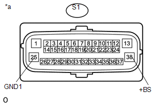
*a |
Front view of wire harness connector (to Skid Control ECU [Brake Actuator Assembly]) |
| NG | |
REPAIR OR REPLACE HARNESS OR CONNECTOR (+BS, GND1 CIRCUIT) |
|
|
3. |
RECONFIRM DTC |
(a) Reconnect the S1 skid control ECU (brake actuator assembly) connector.
(b) Clear the DTCs (See page
).
(c) Turn the ignition switch off.
(d) Start the engine.
(e) Perform a road test.
(f) Check if the same DTC is recorded (See page
).
|
Result |
Proceed to |
|---|---|
|
DTC C1417 is not output |
A |
|
DTC C1417 is output |
B |
| A | |
USE SIMULATION METHOD TO CHECK |
| B | |
REPLACE BRAKE ACTUATOR ASSEMBLY |
 Rear Speed Sensor RH Output Malfunction (C1415,C1416)
DESCRIPTION
Refer to DTCs C1403 and C1404 (See page ).
DTC No.
Detection Item
DTC Detection Condition
Trouble Area
C1415
Rear ...
 Acceleration Sensor Internal Circuit (C1419,C1435)
DESCRIPTION
The skid control ECU (brake actuator assembly) receives signals from the yaw
rate and acceleration sensor (airbag sensor assembly) via the CAN communication
system.
The airbag sensor ...
Other materials:
Diagnostic Trouble Code Chart
DIAGNOSTIC TROUBLE CODE CHART
Forward Recognition Camera System
DTC No.
Detection Item
Link
C1A0A
Front Radar Sensor Region Code Mismatch
C1A47
Steering Angle Sensor
...
Power Outlet Socket(for Rear Side)
Components
COMPONENTS
ILLUSTRATION
*1
USB CHARGER SOCKET
-
-
Removal
REMOVAL
PROCEDURE
1. REMOVE REAR CONSOLE BOX ASSEMBLY
Click here
2. REMOVE USB CHARGER SOCKET
(a) Disengage the 4 claws to remove the USB charger soc ...
Combination Meter
Components
COMPONENTS
ILLUSTRATION
Removal
REMOVAL
PROCEDURE
1. PRECAUTION
NOTICE:
After turning the ignition switch off, waiting time may be required before disconnecting
the cable from the negative (-) battery terminal. Therefore, make sure to read the
disconnecting the cable fro ...
