Toyota Tacoma (2015-2018) Service Manual: Front Passenger Side Seat Belt Warning Light Malfunction
DESCRIPTION
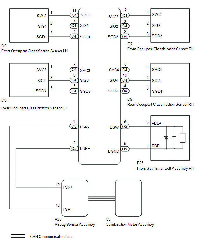
The occupant classification ECU detects the state of the front seat inner belt assembly RH and load sensor when the front passenger side seat is occupied with the ignition switch ON. If the front passenger side seat belt is not fastened, the front passenger side seat belt warning light on the combination meter assembly blinks. If the seat belt is fastened, the warning light goes off.
WIRING DIAGRAM
PROCEDURE
|
1. |
CHECK DTC OUTPUT (OCCUPANT CLASSIFICATION SYSTEM) |
(a) Clear the DTCs (See page .gif) ).
).
(b) Check for DTCs (See page ).
|
Result |
Proceed to |
|---|---|
|
DTCs are not output |
A |
|
DTCs are output |
B |
| B | .gif) |
GO TO OCCUPANT CLASSIFICATION SYSTEM |
|
.gif)
|
2. |
CHECK DTC OUTPUT (AIRBAG SYSTEM) |
(a) Clear the DTCs (See page ).
(b) Check for DTCs (See page ).
|
Result |
Proceed to |
|---|---|
|
DTCs are not output |
A |
|
DTCs are output |
B |
| B | |
GO TO AIRBAG SYSTEM |
|
|
3. |
READ VALUE USING TECHSTREAM (PASSENGER BUCKLE SW) |
(a) Connect the Techstream to the DLC3.
(b) Turn the ignition switch to ON.
(c) Turn the Techstream on.
(d) Enter the following menus: Body Electrical / Occupant Detection / Data List.
(e) Read the Data List according to the display on the Techstream.
Occupant Detection|
Tester Display |
Measurement Item/Range |
Normal Condition |
Diagnostic Note |
|---|---|---|---|
|
Passenger Buckle SW |
Front passenger side seat belt buckle switch/Unset, Set or NG |
Unset: Front passenger side seat belt unfastened Set: Front passenger side seat belt fastened NG: Data not determined |
- |
|
Result |
Proceed to |
|---|---|
|
Unset or Set is displayed on the Techstream according to the front passenger seat belt condition |
A |
|
Unset or Set is not displayed correctly on the Techstream according to the front passenger seat belt condition |
B |
|
NG is displayed on the Techstream |
C |
| B | |
REPLACE FRONT SEAT INNER BELT ASSEMBLY RH |
| C | |
REPLACE OCCUPANT CLASSIFICATION ECU |
|
|
4. |
READ VALUE USING TECHSTREAM (RIGHT SIDE BUCKLE SW) |
(a) Connect the Techstream to the DLC3.
(b) Turn the ignition switch to ON.
(c) Turn the Techstream on.
(d) Enter the following menus: Body Electrical / SRS Airbag / Data List.
(e) Read the Data List according to the display on the Techstream.
SRS Airbag|
Tester Display |
Measurement Item/Range |
Normal Condition |
Diagnostic Note |
|---|---|---|---|
|
Right side Buckle SW |
Front passenger side seat belt buckle switch/Unset, Set or NG |
Unset: Front passenger side seat belt unfastened Set: Front passenger side seat belt fastened NG: Data not determined |
- |
|
Result |
Proceed to |
|---|---|
|
Unset or Set is displayed on the Techstream according to the front passenger seat belt condition |
A |
|
B |
| A | |
USE SIMULATION METHOD TO CHECK |
| B | |
REPLACE AIRBAG SENSOR ASSEMBLY |
 On-vehicle Inspection
ON-VEHICLE INSPECTION
PROCEDURE
1. INSPECT DRIVER SEAT BELT WARNING LIGHT
HINT:
The seat belt warning light on the combination meter assembly is used for both
the driver seat and front passenger ...
 Sliding Roof
...
Other materials:
Dtc Check / Clear
DTC CHECK / CLEAR
1. CHECK DTC
(a) Connect the Techstream to the DLC3.
(b) Turn the ignition switch to ON.
(c) Turn the back sonar or clearance sonar switch assembly on.
(d) Turn the Techstream on.
(e) Enter the following menus: Body Electrical / Intuitive P/A / Trouble Codes.
(f) Check for D ...
Short to +B in Buzzer (C1ABD,C1ABE)
DESCRIPTION
DTC C1ABD is stored when the blind spot monitor sensor RH detects a
+B short in rear cross traffic alert buzzer (blind spot monitor buzzer)
circuit.
DTC C1ABE is stored when the blind spot monitor sensor RH detects a
ground short or open in rear cross traffic aler ...
Installation
INSTALLATION
CAUTION / NOTICE / HINT
HINT:
Perform "Inspection After Repairs" after replacing the fuel pump assembly (See
page ).
PROCEDURE
1. SET FUEL PUMP ASSEMBLY
HINT:
Perform "Inspection After Repairs" after replacing the fuel pump assembly (See
page ).
...
