Toyota Tacoma (2015-2018) Service Manual: Front Camera Module Communication Stop Mode
DESCRIPTION
|
Detection Item |
Symptom |
Trouble Area |
|---|---|---|
|
Front Camera Module Communication Stop Mode |
Either Condition is met:
|
|
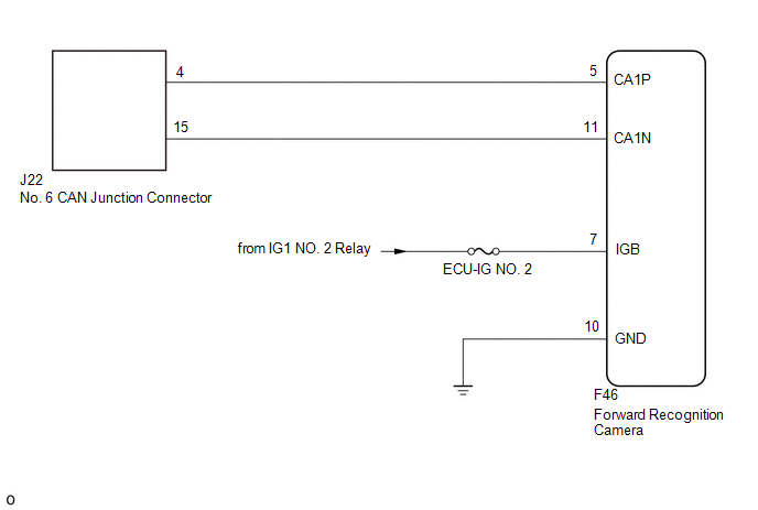
WIRING DIAGRAM
CAUTION / NOTICE / HINT
CAUTION:
When performing the confirmation driving pattern, obey all speed limits and traffic laws.
NOTICE:
- Because the order of diagnosis is important to allow correct diagnosis,
make sure to begin troubleshooting using How to Proceed with Troubleshooting
when CAN communication system related DTCs are output.
Click here
.gif)
- Before measuring the resistance of the CAN bus, turn the ignition switch off and leave the vehicle for 1 minute or more without operating the key or any switches, or opening or closing the doors. After that, disconnect the cable from the negative (-) battery terminal and leave the vehicle for 1 minute or more before measuring the resistance.
- After turning the ignition switch off, waiting time may be required
before disconnecting the cable from the negative (-) battery terminal. Therefore,
make sure to read the disconnecting the cable from the negative (-) battery
terminal notices before proceeding with work.
Click here
- Some parts must be initialized and set when replacing or removing and
installing parts.
Click here
- After performing repairs, perform the DTC check procedure and confirm
that the DTCs are not output again.
DTC check procedure: Turn the ignition switch to ON and wait for 1 minute or more. Then operate the suspected malfunctioning system and drive the vehicle at 60 km/h (37 mph) or more for 5 minutes or more.
- After the repair, perform the CAN bus check and check that all the ECUs
and sensors connected to the CAN communication system are displayed as normal.
Click here
- Inspect the fuses for circuits related to this system before performing the following procedure.
HINT:
- Before disconnecting related connectors for inspection, push in on each connector body to check that the connector is not loose or disconnected.
- When a connector is disconnected, check that the terminals and connector body are not cracked, deformed or corroded.
PROCEDURE
|
1. |
CHECK FOR OPEN IN CAN BUS LINES (FORWARD RECOGNITION CAMERA CAN BRANCH LINE) |
|
(a) Disconnect the cable from the negative (-) battery terminal. |
|
(b) Disconnect the forward recognition camera connector.
(c) Measure the resistance according to the value(s) in the table below.
Standard Resistance:
|
Tester Connection |
Condition |
Specified Condition |
|---|---|---|
|
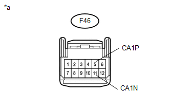
F46-5 (CA1P) - F46-11 (CA1N) |
Cable disconnected from negative (-) battery terminal |
54 to 69 Ω |
|
*a |
Front view of wire harness connector (to Forward Recognition Camera) |
| NG | .gif) |
REPAIR OR REPLACE CAN BRANCH LINE OR CONNECTOR (FORWARD RECOGNITION CAMERA) |
|
.gif)
|
2. |
CHECK HARNESS AND CONNECTOR (POWER SOURCE CIRCUIT) |
|
(a) Measure the resistance according to the value(s) in the table below. Standard Resistance:
|
|
(b) Connect the cable to the negative (-) battery terminal.
(c) Measure the voltage according to the value(s) in the table below.
Standard Voltage:
|
Tester Connection |
Switch Condition |
Specified Condition |
|---|---|---|
|
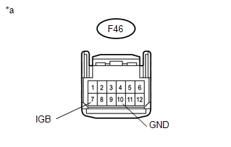
F46-7 (IGB) - Body ground |
Ignition switch ON |
11 to 14 V |
|
*a |
Front view of wire harness connector (to Forward Recognition Camera) |
| OK | |
REPLACE FORWARD RECOGNITION CAMERA |
| NG | |
REPAIR OR REPLACE HARNESS OR CONNECTOR |
 Open in One Side of Bus 5 Branch Line
DESCRIPTION
When the CAN bus main lines are normal (no open, short to ground, short to +B
or short between lines) and there is an ECU or sensor on the "Communication Bus
Check" screen t ...
 Tire Pressure Monitor ECU Communication Stop Mode
DESCRIPTION
Detection Item
Symptom
Trouble Area
Tire Pressure Monitor ECU Communication Stop Mode
Either condition is met:
C ...
Other materials:
Installation
INSTALLATION
PROCEDURE
1. SET NO. 1 CYLINDER TO TDC/COMPRESSION
2. INSTALL CAMSHAFT TIMING GEAR BOLT
NOTICE:
There are different types of camshaft timing gear bolts. Make sure to check the
identification mark to determine the tightening torque.
*a
Identification Ma ...
Satellite Radio Broadcast cannot be Received
CAUTION / NOTICE / HINT
NOTICE:
Some satellite radio broadcasts require payment. A contract must be
made between a satellite radio company and the user. If the contract expires,
it will not be possible to listen to the broadcast.
After replacing the stereo component tuner assem ...
Pressure Control Solenoid "B" Actuator Stuck Off (P07757F)
SYSTEM DESCRIPTION
The ECM uses the vehicle speed signal and signals from the transmission revolution
sensors (NT, SP2) to detect the actual gear (1st, 2nd, 3rd, 4th, 5th or 6th gear).
The ECM compares the actual gear with the shift schedule in the ECM memory to
detect mechanical problems of t ...
