Toyota Tacoma (2015-2018) Service Manual: Evaporator Temperature Sensor Circuit (B1413/13)
DESCRIPTION
The cooler thermistor sensor (evaporator temperature sensor) is installed on the evaporator in the air conditioner unit to detect the temperature of the cooled air that has passed through the evaporator and is used to control the air conditioning. It sends signals to the air conditioning amplifier assembly. The resistance of the cooler thermistor sensor (evaporator temperature sensor) changes in accordance with the temperature of the cooled air that has passed through the evaporator. As the temperature decreases, the resistance increases. As the temperature increases, the resistance decreases.
The air conditioning amplifier assembly applies voltage (5 V) to the cooler thermistor sensor (evaporator temperature sensor) and reads voltage changes as the resistance of the cooler thermistor sensor (evaporator temperature sensor) changes. This sensor is used for frost prevention.
|
DTC No. |
DTC Detection Condition |
Trouble Area |
|---|---|---|
|
B1413/13 |
Open or short in cooler thermistor sensor (evaporator temperature sensor) circuit |
|
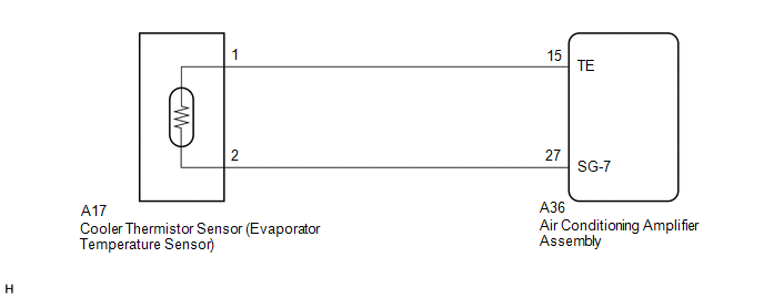
WIRING DIAGRAM
PROCEDURE
|
1. |
READ VALUE USING TECHSTREAM |
(a) Connect the Techstream to the DLC3.
(b) Turn the ignition switch to ON.
(c) Turn the Techstream on.
(d) Enter the following menus: Body Electrical / Air Conditioner / Data List.
(e) Check the value(s) by referring to the table below.
Air Conditioner|
Tester Display |
Measurement Item/Range |
Normal Condition |
Diagnostic Note |
|---|---|---|---|
|
Evaporator Fin Thermistor |
Cooler thermistor sensor (Evaporator temperature sensor) / Min.: -29.70°C (-21.46°F) Max.: 59.55°C (139.19°F) |
Actual evaporator temperature displayed |
- |
OK:
The display is as specified in the Normal Condition column.
|
Result |
Proceed to |
|---|---|
|
NG |
A |
|
OK (When troubleshooting according to Problem Symptoms Table) |
B |
|
OK (When troubleshooting according to the DTC) |
C |
| B | .gif) |
PROCEED TO NEXT SUSPECTED AREA SHOWN IN PROBLEM SYMPTOMS TABLE |
| C | |
REPLACE AIR CONDITIONING AMPLIFIER ASSEMBLY |
|
.gif)
|
2. |
INSPECT COOLER THERMISTOR SENSOR (EVAPORATOR TEMPERATURE SENSOR) |
(a) Remove the cooler thermistor sensor (evaporator temperature sensor) (See
page .gif) ).
).
(b) Inspect the cooler thermistor sensor (evaporator temperature sensor) (See
page ).
| NG | |
REPLACE COOLER THERMISTOR SENSOR (EVAPORATOR TEMPERATURE SENSOR) |
|
|
3. |
CHECK HARNESS AND CONNECTOR (COOLER THERMISTOR SENSOR (EVAPORATOR TEMPERATURE SENSOR) - AIR CONDITIONING AMPLIFIER ASSEMBLY) |
(a) Disconnect the A17 cooler thermistor sensor (evaporator temperature sensor) connector.
(b) Disconnect the A36 air conditioning amplifier assembly connector.
(c) Measure the resistance according to the value(s) in the table below.
Standard Resistance:
|
Tester Connection |
Condition |
Specified Condition |
|---|---|---|
|
A36-15 (TE) - A17-2 |
Always |
Below 1 Ω |
|
A36-27 (SG-7) - A17-1 |
Always |
Below 1 Ω |
|
A36-15 (TE) or A17-2 - Body ground |
Always |
10 kΩ or higher |
|
A36-27 (SG-7) or A17-1 - Body ground |
Always |
10 kΩ or higher |
| OK | |
REPLACE AIR CONDITIONING AMPLIFIER ASSEMBLY |
| NG | |
REPAIR OR REPLACE HARNESS OR CONNECTOR |
 Ambient Temperature Sensor Circuit (B1412/12)
DESCRIPTION
The ambient temperature sensor is installed in front of the condenser to detect
the ambient temperature which is used to control the air conditioning system AUTO
mode. This sensor is ...
 Compressor Lock Sensor Circuit (B1422/22)
SYSTEM DESCRIPTION
The ECM sends the engine speed signal to the air conditioning amplifier assembly
via CAN communication.
The air conditioning amplifier assembly reads the difference between comp ...
Other materials:
Dtc Check / Clear
DTC CHECK / CLEAR
1. CHECK DTC
(a) Connect the Techstream to the DLC3.
(b) Turn the ignition switch to ON.
(c) Turn the Techstream on.
(d) Enter the following menus: Body Electrical / Trouble Codes.
(e) Check DTCs and then write them down.
HINT:
Refer to the Techstream operator's manual ...
Data List / Active Test
DATA LIST / ACTIVE TEST
1. READ DATA LIST
HINT:
Using the Techstream to read the Data List allows the values or states of switches,
sensors, actuators and other items to be read without removing any parts. This non-intrusive
inspection can be very useful because intermittent conditions or sig ...
Check Mode Procedure
CHECK MODE PROCEDURE
1. DESCRIPTION
Check mode has a higher sensitivity to malfunctions and can detect malfunctions
that cannot be detected in normal mode. Check mode can also detect all of the malfunctions
that can be detected in normal mode. In check mode, DTCs are stored with 1 trip
detec ...
