Toyota Tacoma (2015-2018) Service Manual: Compressor Lock Sensor Circuit (B1422/22)
SYSTEM DESCRIPTION
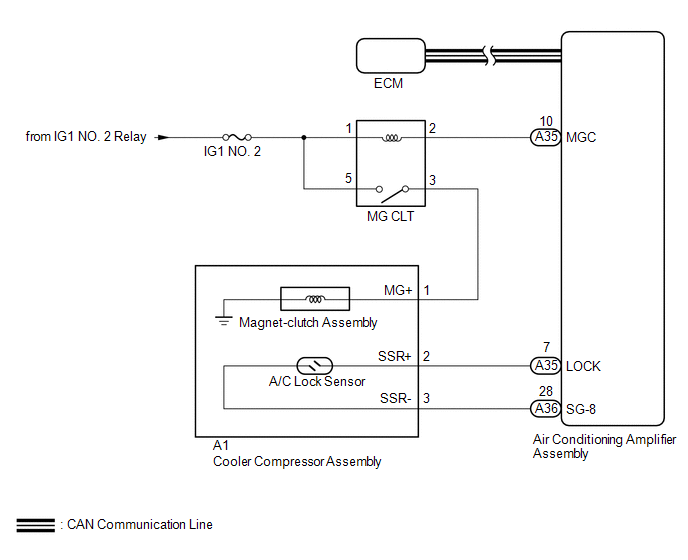
The ECM sends the engine speed signal to the air conditioning amplifier assembly via CAN communication.
The air conditioning amplifier assembly reads the difference between compressor speed and engine speed. When the difference becomes too large, the air conditioning amplifier assembly determines that the compressor is locked, and turns the magnet-clutch assembly off.
|
DTC No. |
DTC Detection Condition |
Trouble Area |
|---|---|---|
|
B1422/22 |
Open or short in A/C lock sensor circuit |
|
WIRING DIAGRAM
CAUTION / NOTICE / HINT
NOTICE:
- ECM malfunctions can affect the storage of this DTC. Therefore, check
all SFI system DTCs and confirm that the system is normal before performing
the following inspection (See page
.gif) ).
).
- Inspect the fuses for circuits related to this system before performing the following procedure.
PROCEDURE
|
1. |
CHECK FOR DTC (CAN COMMUNICATION SYSTEM) |
(a) Use the Techstream to check if the CAN communication system is functioning normally.
Result|
Result |
Proceed to |
|---|---|
|
CAN DTC is not output |
A |
|
CAN DTC is output |
B |
| NG | .gif) |
GO TO CAN COMMUNICATION SYSTEM |
|
.gif)
|
2. |
INSPECT A/C LOCK SENSOR |
(a) Remove the A/C lock sensor (See page ).
(b) Inspect the A/C lock sensor (See page ).
| NG | |
REPLACE A/C LOCK SENSOR |
|
|
3. |
CHECK HARNESS AND CONNECTOR (AIR CONDITIONING AMPLIFIER ASSEMBLY - COOLER COMPRESSOR ASSEMBLY) |
(a) Disconnect the A1 cooler compressor assembly connector.
(b) Disconnect the A35 and A36 air conditioning amplifier assembly connectors.
(c) Measure the resistance according to the value(s) in the table below.
Standard Resistance:
|
Tester Connection |
Condition |
Specified Condition |
|---|---|---|
|
A35-7 (LOCK) - A1-2 (SSR+) |
Always |
Below 1 Ω |
|
A36-28 (SG-8) - A1-3 (SSR-) |
Always |
Below 1 Ω |
|
A35-7 (LOCK) or A1-2 (SSR+) - Body ground |
Always |
10 kΩ or higher |
|
A36-28 (SG-8) or A1-3 (SSR-) - Body ground |
Always |
10 kΩ or higher |
|
Result |
Proceed to |
|---|---|
|
NG |
A |
|
OK (When troubleshooting according to Problem Symptoms Table) |
B |
|
OK (When troubleshooting according to the DTC) |
C |
| A | |
REPAIR OR REPLACE HARNESS OR CONNECTOR |
| B | |
PROCEED TO NEXT SUSPECTED AREA SHOWN IN PROBLEM SYMPTOMS TABLE |
| C | |
REPLACE AIR CONDITIONING AMPLIFIER ASSEMBLY |
 Evaporator Temperature Sensor Circuit (B1413/13)
DESCRIPTION
The cooler thermistor sensor (evaporator temperature sensor) is installed on
the evaporator in the air conditioner unit to detect the temperature of the cooled
air that has passed thr ...
 Air Conditioning Compressor Magnetic Clutch Circuit
DESCRIPTION
When the air conditioning amplifier assembly is turned on, a magnetic clutch
on signal is sent from the MGC terminal of the air conditioning amplifier assembly.
Then, the MG CLT relay ...
Other materials:
Transmission Fluid Temperature Sensor "B" Circuit Short to Battery or Open (P274015)
DESCRIPTION
The No. 2 ATF temperature sensor is installed in the transmission valve body
assembly.
If the ECM detects an abnormally high ATF temperature near this sensor, it illuminates
the warning indicator.
HINT:
The temperature of ATF easily rises when towing, climbing hills, in traffic, ...
Components
COMPONENTS
ILLUSTRATION
*A
w/ Off Road Package
-
-
*1
NO. 1 ENGINE UNDER COVER SUB-ASSEMBLY
*2
NO. 2 ENGINE UNDER COVER SUB-ASSEMBLY
*3
FRONT UPPER FENDER APRON SEAL
...
Inspection
INSPECTION
PROCEDURE
1. INSPECT FRONT SEAT INNER BELT ASSEMBLY LH
(a) Check the resistance.
(1) Measure the resistance according to the value(s) in the table below.
Standard resistance:
Tester Connection
Condition
Specified C ...
