Toyota Tacoma (2015-2018) Service Manual: Engine Immobiliser System Signal (Some Circuit Quantity, Reported via Serial Data) Invalid (B279986)
DESCRIPTION
When there are communication malfunctions between the ECM and certification ECU (smart key ECU assembly), or when the communication ID codes do not match, the ECM stores this DTC.
|
DTC Code |
DTC Detection Condition |
Trouble Area |
DTC Output Confirmation Operation |
|---|---|---|---|
|
B279986 |
Either condition is met (1 trip detection logic*1):
|
|
Either condition is met:
|
- *1: Only output while a malfunction is present.
|
Vehicle Condition when Malfunction Detected |
Fail-safe Operation when Malfunction Detected |
|---|---|
|
Engine cannot be started |
- |
|
DTC Code |
Data List and Active Test |
|---|---|
|
B279986 |
- |
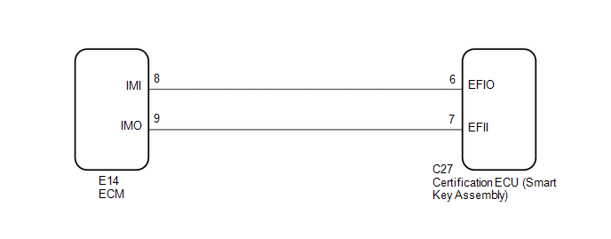
WIRING DIAGRAM
CAUTION / NOTICE / HINT
NOTICE:
- When replacing the certification ECU (smart key ECU assembly), refer
to Registration (See page
.gif) .
. - After performing repairs, perform the operation that fulfills the DTC output confirmation operation, and then confirm that no DTCs are output again.
HINT:
When DTC B279986 and the certification ECU (smart key ECU assembly) DTC are output simultaneously, first perform troubleshooting for the certification ECU (smart key ECU assembly) DTC.
PROCEDURE
|
1. |
REGISTER ECU COMMUNICATION ID |
(a) Register the ECU communication ID (See page
).
|
.gif)
|
2. |
CLEAR DTC |
(a) Clear the DTCs (See page ).
|
|
3. |
CHECK FOR DTC |
(a) Start the engine.
(b) Perform "DTC Output Confirmation Operation" procedure.
(c) Check for DTCs (See page ).
OK:
DTC B279986 is not output.
Result|
Result |
Proceed to |
|---|---|
|
OK |
A |
|
NG (DTC B279986 is output) |
B |
|
NG (Other DTCs are output) |
C |
| A | .gif) |
END (COMMUNICATION ID REGISTRATION WAS DEFECTIVE) |
| C | |
GO TO DIAGNOSTIC TROUBLE CODE CHART |
|
|
4. |
INSPECT ECM (TERMINAL IMO) |
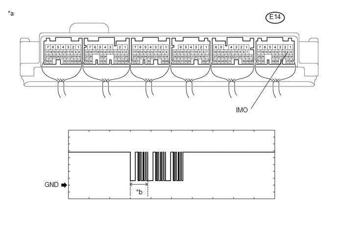
(a) Using an oscilloscope, check the waveform.
 Text in Illustration
|
*a |
Component with harness connected (ECM) |
*b |
Waveform |
Measurement Condition:
|
Tester Connection |
Condition |
Tool Setting |
Specified Condition |
|---|---|---|---|
|
E14-9 (IMO) - Body ground |
Within 3 seconds of engine start or within 3 seconds of engine switch turned on (IG) after battery cable disconnected and reconnected |
2 V/DIV., 500 ms./DIV. |
Pulse generation (See waveform) |
OK:
The waveform is similar to that shown in the illustration.
Result|
Result |
Proceed to |
|---|---|
|
Normal waveform |
A |
|
Terminal IMO stuck low (2.4 V or less) |
B |
|
Terminal IMO stuck high (12 V), or has abnormal wavelength or shape |
C |
| B | |
GO TO STEP 8 |
| C | |
REPLACE ECM |
|
|
5. |
INSPECT CERTIFICATION ECU (SMART KEY ECU ASSEMBLY) (TERMINAL IMI) |
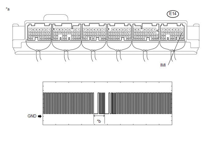
(a) Using an oscilloscope, check the waveform.
 Text in Illustration
|
*a |
Component with harness connected (ECM) |
*b |
Waveform |
Measurement Condition:
|
Tester Connection |
Condition |
Tool Setting |
Specified Condition |
|---|---|---|---|
|
E14-8 (IMI) - Body ground |
Engine switch on (IG) using registered electrical key transmitter sub-assembly |
2 V/DIV., 500 ms./DIV. |
Pulse generation (See waveform) |
OK:
The waveform is similar to that shown in the illustration.
| NG | |
REPLACE CERTIFICATION ECU (SMART KEY ECU ASSEMBLY) |
|
|
6. |
REGISTER ECU COMMUNICATION ID |
(a) Register the ECU communication ID (See page
).
|
|
7. |
CHECK WHETHER ENGINE STARTS |
(a) Using an electrical key transmitter sub-assembly which is registered to the vehicle, turn the engine switch on (IG).
(b) Check that the engine starts 5 seconds after the engine switch was turned on (IG).
OK:
Engine starts normally.
| OK | |
END (COMMUNICATION ID REGISTRATION WAS DEFECTIVE) |
| NG | |
REPLACE ECM |
|
8. |
INSPECT ECM (IMO TERMINAL VOLTAGE) |
|
(a) Disconnect the ECM connector. |
|
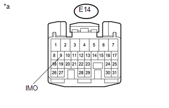
(b) Turn the engine switch on (IG).
(c) Measure the voltage according to the value(s) in the table below.
Standard Voltage:
|
Tester Connection |
Condition |
Specified Condition |
|---|---|---|
|
E14-9 (IMO) - Body ground |
Engine switch on (IG) using registered electrical key transmitter sub-assembly |
Terminal IMO stuck low (2.4 V or less) |
|
Terminal IMO stuck high (12 V) or abnormal waveform |
|
*a |
Front view of wire harness connector (to ECM) |
|
Result |
Proceed to |
|---|---|
|
Terminal IMO stuck low (2.4 V or less) |
A |
|
Terminal IMO stuck high (12 V) or abnormal waveform |
B |
| B | |
REPLACE ECM |
|
|
9. |
CHECK HARNESS AND CONNECTOR (CERTIFICATION ECU (SMART KEY ECU ASSEMBLY) - ECM) |
(a) Disconnect the C27 certification ECU (smart key ECU assembly) connector.
(b) Disconnect the E14 ECM connector.
(c) Measure the resistance according to the value(s) in the table below.
Standard Resistance:
|
Tester Connection |
Condition |
Specified Condition |
|---|---|---|
|
C27-7 (EFII) - E14-9 (IMO) |
Always |
Below 1 Ω |
|
C27-7 (EFII) or E14-9 (IMO) - Body ground |
Always |
10 kΩ or higher |
|
C27-6 (EFIO) - E14-8 (IMI) |
Always |
Below 1 Ω |
|
C27-6 (EFIO) or E14-8 (IMI) - Body ground |
Always |
10 kΩ or higher |
| OK | |
REPLACE CERTIFICATION ECU (SMART KEY ECU ASSEMBLY) |
| NG | |
REPAIR OR REPLACE HARNESS OR CONNECTOR |
 Antenna Coil Open / Short (B2784)
DESCRIPTION
When an open or short circuit is detected in the transponder key amplifier coil
built into the engine switch, the certification ECU (smart key ECU assembly) stores
this DTC. This DTC ...
 Malfunction of ID-BOX Recognition (B278D)
DESCRIPTION
When the certification ECU (smart key ECU assembly) detects an input signal indicating
that the vehicle is equipped with an ID code box even though the ID code box is
not registered, ...
Other materials:
Abnormal Change in Output Signal of Rear Speed Sensor RH (Test Mode DTC) (C1277,...,C1416)
DESCRIPTION
Refer to DTCs C1401 and C1402 (See page ).
DTC Code
DTC Detection Condition
Trouble Area
C1277
C1278
Stored only during test mode.
Rear speed sensor RH/LH
Rear speed sensor rotor RH/LH (Rear ax ...
Reassembly
REASSEMBLY
PROCEDURE
1. INSTALL UPPER RADIATOR TANK
(a) Install a new upper radiator tank.
Text in Illustration
*1
Upper Radiator Tank
*2
Core Plate
*a
Correc ...
Output Shaft
Components
COMPONENTS
ILLUSTRATION
Disassembly
DISASSEMBLY
PROCEDURE
1. REMOVE FRONT OUTPUT SHAFT BEARING
(a) Temporarily install the manual transmission output shaft rear set
nut to the output shaft.
Text in Illustration
*1
Manual ...
