Toyota Tacoma (2015-2018) Service Manual: Engine does not Start because No Initial Combustion
DESCRIPTION
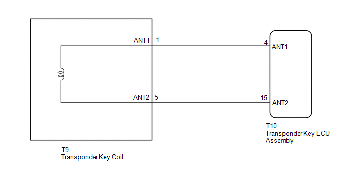
- When a key is inserted into the ignition key cylinder, the transponder key coil receives the key ID code and sends it to the transponder key ECU assembly.
- If an error in communication between the transponder key coil and transponder key ECU assembly occurs, this symptom may occur.
WIRING DIAGRAM
CAUTION / NOTICE / HINT
NOTICE:
If the transponder key ECU assembly or key is replaced, refer to Registration
(See page .gif) ).
).
PROCEDURE
|
1. |
CLEAR DTC |
(a) Clear the DTCs (See page ).
|
.gif)
|
2. |
CHECK FOR DTC |
(a) Check for DTCs (See page ).
|
Result |
Proceed to |
|---|---|
|
DTCs are not output |
A |
|
DTCs are output |
B |
| B | .gif) |
GO TO DIAGNOSTIC TROUBLE CODE CHART |
|
|
3. |
READ VALUE USING TECHSTREAM (IMMOBILISER FUEL CUT) |
(a) Connect the Techstream to the DLC3.
(b) Turn the ignition switch to ON.
(c) Turn the Techstream on.
(d) Enter the following menus: Powertrain / Engine and ECT or Engine / Data List.
(e) Read the Data List according to the display on the Techstream.
Engine and ECT (for 2TR-FE)|
Tester Display |
Measurement Item/Range |
Normal Condition |
Diagnostic Note |
|---|---|---|---|
|
Immobiliser Fuel Cut |
Status of immobiliser fuel cut / ON or OFF |
- |
- |
|
Tester Display |
Measurement Item/Range |
Normal Condition |
Diagnostic Note |
|---|---|---|---|
|
Immobiliser Fuel Cut |
Status of immobiliser fuel cut / ON or OFF |
- |
- |
OK:
OFF is displayed after the ignition switch is turned ON.
Result|
Result |
Proceed to |
|---|---|
|
NG |
A |
|
OK (for 2TR-FE) |
B |
|
OK (for 2GR-FKS) |
C |
| B | |
GO TO SFI SYSTEM |
| C | |
GO TO SFI SYSTEM |
|
|
4. |
CHECK SECURITY INDICATOR LIGHT OPERATION |
(a) Check that the security indicator light turns off when a registered key is inserted into the ignition key cylinder.
OK:
Security indicator light turns off.
Result|
Result |
Proceed to |
|---|---|
|
NG |
A |
|
OK |
B |
| B | |
GO TO OTHER DIAGNOSIS PROCEDURE (Engine does not Start but Initial Combustion Occurs) |
|
|
5. |
CHECK SECURITY INDICATOR LIGHT OPERATION |
(a) Check that the security indicator light turns off when another registered key is inserted into the ignition key cylinder.
OK:
Security indicator light turns off.
| NG | |
GO TO STEP 7 |
|
|
6. |
CHECK WHETHER ENGINE STARTS |
(a) Using another registered key, turn the ignition switch to ON.
(b) Check that the engine starts 5 seconds after the ignition switch was turned to ON.
OK:
Engine starts normally.
Result|
Result |
Proceed to |
|---|---|
|
Engine cannot be started |
A |
|
Engine can be started |
B |
| A | |
GO TO OTHER DIAGNOSIS PROCEDURE (Engine does not Start but Initial Combustion Occurs) |
| B | |
GO TO STEP 11 |
|
7. |
REPLACE TRANSPONDER KEY COIL |
(a) Replace the transponder key coil (See page
).
|
|
8. |
CHECK WHETHER ENGINE STARTS |
(a) Using another registered key, turn the ignition switch to ON.
(b) Check that the engine starts 5 seconds after the ignition switch was turned to ON.
OK:
Engine starts normally.
Result|
Result |
Proceed to |
|---|---|
|
Engine can be started |
A |
|
Engine cannot be started |
B |
| A | |
END (TRANSPONDER KEY COIL WAS DEFECTIVE) |
|
|
9. |
REPLACE TRANSPONDER KEY ECU ASSEMBLY |
(a) Replace the transponder key ECU assembly with a new one (See page
).
NOTICE:
Key ID code registration is necessary when replacing the transponder key ECU
assembly, refer to Registration (See page ).
|
|
10. |
CHECK WHETHER ENGINE STARTS |
(a) Using another registered key, turn the ignition switch to ON.
(b) Check that the engine starts 5 seconds after the ignition switch was turned to ON.
OK:
Engine starts normally.
Result|
Result |
Proceed to |
|---|---|
|
Engine can be started |
A |
|
Engine cannot be started |
B |
| A | |
END (TRANSPONDER KEY ECU ASSEMBLY WAS DEFECTIVE) |
|
|
11. |
REPLACE KEY |
(a) Replace the key.
NOTICE:
Key ID code registration is necessary when replacing the key, refer to Registration
(See page ).
|
|
12. |
CHECK WHETHER ENGINE STARTS |
(a) Using another registered key, turn the ignition switch to ON.
(b) Check that the engine starts 5 seconds after the ignition switch was turned to ON.
OK:
Engine starts normally.
Result|
Result |
Proceed to |
|---|---|
|
Engine can be started |
A |
|
Engine cannot be started (for 2TR-FE) |
B |
|
Engine cannot be started (for 2GR-FKS) |
C |
| A | |
END (KEY WAS DEFECTIVE) |
| B | |
GO TO SFI SYSTEM |
| C | |
GO TO SFI SYSTEM |
 Transponder Chip Malfunction (B2793,B2794,B2797,B2798)
DESCRIPTION
DTC B2793 is stored when a malfunction is found in the key during key
code registration or a key code is not registered normally. Replace the
key if key code registration c ...
 Engine does not Start but Initial Combustion Occurs
DESCRIPTION
If the key ID codes of the key and transponder key ECU assembly match, the engine
immobiliser system is unset and the engine start permission signal is sent to the
ECM. When the ID co ...
Other materials:
Removal
REMOVAL
CAUTION / NOTICE / HINT
NOTICE:
When replacing the forward recognition camera, replace it with a new
one.
Do not touch the camera lens or the front windshield glass in front
of the camera.
If the forward recognition camera has been struck or dropped, replace
it ...
Installation
INSTALLATION
PROCEDURE
1. INSTALL STEERING PAD
(a) Check that the ignition switch is off.
(b) Check that the cable is disconnected from the negative (-) battery terminal.
CAUTION:
Wait at least 90 seconds after disconnecting the cable from the negative (-)
battery terminal to disable the SRS ...
Open or Short Circuit in Back Camera Signal (C1622)
DESCRIPTION
This DTC is stored if the radio and display receiver assembly*1 or navigation
receiver assembly*2 judges as a result of its self check that the signals or signal
lines between the radio and display receiver assembly*1 or navigation receiver assembly*2
and the rear television camer ...
