Toyota Tacoma (2015-2018) Service Manual: Installation
INSTALLATION
PROCEDURE
1. INSTALL TRANSMISSION CONTROL CABLE ASSEMBLY
(a) Install the transmission control cable assembly from outside the vehicle body and attach the 3 claws of the cable retainer.
(b) Install the 2 nuts.
Torque:
5.5 N·m {56 kgf·cm, 49 in·lbf}
(c) Connect the transmission control cable support to the vehicle body with the nut.
Torque:
5.5 N·m {56 kgf·cm, 49 in·lbf}
|
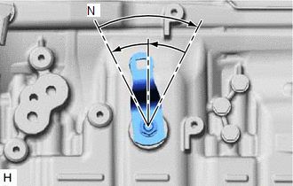
(d) Turn the transmission control shaft lever LH clockwise until it stops, and then return the transmission control shaft lever LH counterclockwise 2 notches to N. |
|
(e) Connect the transmission control cable assembly to the transmission control cable bracket with a new clip, and then connect the cable end to the transmission control shaft lever LH with the nut.
Torque:
14 N·m {143 kgf·cm, 10 ft·lbf}
2. CONNECT TRANSMISSION CONTROL CABLE ASSEMBLY
.gif)
3. INSPECT SHIFT LEVER POSITION
4. REMOVE FRONT CONSOLE BOX
(See page )
 Adjustment
ADJUSTMENT
PROCEDURE
1. REMOVE FRONT CONSOLE BOX
(See page )
2. ADJUST TRANSMISSION CONTROL CABLE ASSEMBLY
(a) Move the shift lever to N.
(b) Disconnect the end of the transmission control cab ...
 Removal
REMOVAL
PROCEDURE
1. REMOVE FRONT CONSOLE BOX
(See page )
2. DISCONNECT TRANSMISSION CONTROL CABLE ASSEMBLY
3. REMOVE TRANSMISSION CONTROL CABLE ASSEMBLY
(a) Remove the nut and c ...
Other materials:
Rear Occupant Classification Sensor RH Circuit Malfunction (B1783)
DESCRIPTION
The rear occupant classification sensor RH circuit consists of the occupant detection
ECU and the rear occupant classification sensor RH.
DTC B1783 is set when a malfunction is detected in the rear occupant classification
sensor RH circuit.
DTC No.
DTC Detect ...
Precaution
PRECAUTION
1. IGNITION SWITCH EXPRESSION
HINT:
The type of ignition switch used on this model differs depending on the specifications
of the vehicle. The expressions listed in the table below are used in this section.
Expression
Ignition Switch (Position)
Engin ...
Removal
REMOVAL
PROCEDURE
1. DRAIN DIFFERENTIAL OIL
2. REMOVE PROPELLER WITH CENTER BEARING SHAFT ASSEMBLY (for 2WD)
3. REMOVE PROPELLER WITH CENTER BEARING SHAFT ASSEMBLY (for 4WD)
4. REMOVE REAR DRIVE PINION NUT
(a) Using SST and a hammer, unstake the nut.
SST: 09930-00010
(b) for BD20:
...
