Toyota Tacoma (2015-2018) Service Manual: Components
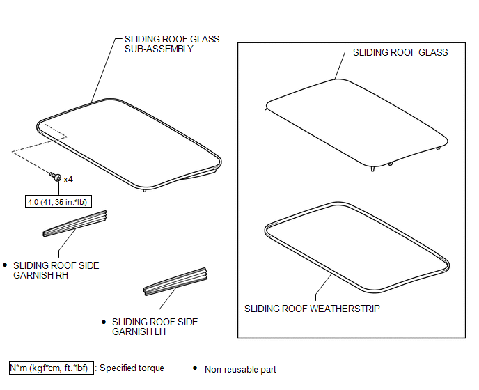
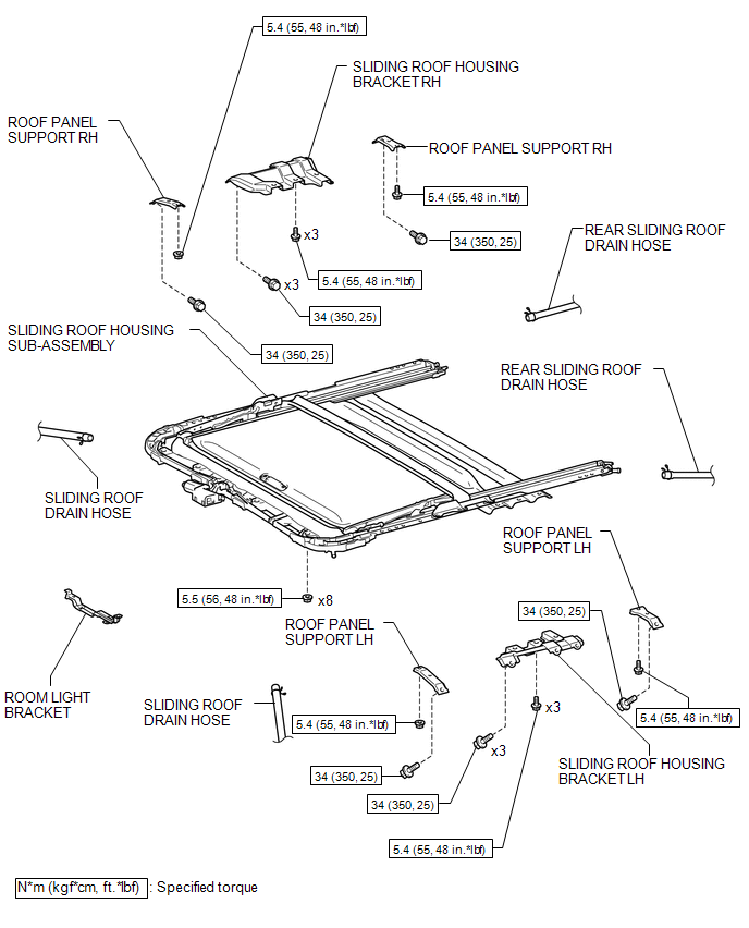
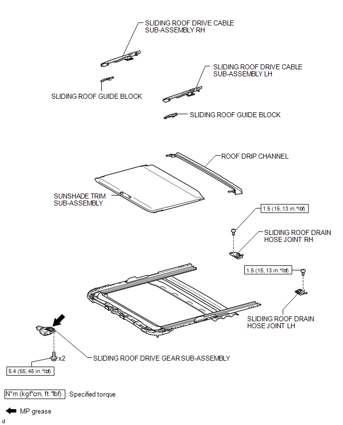
COMPONENTS
ILLUSTRATION
ILLUSTRATION
ILLUSTRATION

 Disassembly
DISASSEMBLY
PROCEDURE
1. REMOVE ROOM LIGHT BRACKET
(a) Disengage the guide to remove the room light bracket.
2. REMOVE SLIDING ROOF DRIVE GEAR ...
Other materials:
Stop Light Control Relay Malfunction (C1380)
DESCRIPTION
The skid control ECU (brake actuator assembly) inputs the stop light switch signal
and detect the status of the brake operation.
DTC No.
Detection Item
DTC Detection Condition
Trouble Area
C1380
Stop Light Contro ...
Removal
REMOVAL
PROCEDURE
1. REMOVE FRONT NO. 2 EXHAUST PIPE ASSEMBLY (for 2GR-FKS)
2. REMOVE PROPELLER SHAFT HEAT INSULATOR BRACKET SUB-ASSEMBLY
(a) Remove the 2 bolts and propeller shaft heat insulator bracket.
3. REMOVE FRONT PROPELLER SHAFT ASSEMBLY
(a) Place matchmarks on the propeller sh ...
Freeze Frame Data
FREEZE FRAME DATA
1. FREEZE FRAME DATA
(a) When a DTC is stored, the 4 wheel drive control ECU stores the current vehicle
state as Freeze Frame Data.
HINT:
Freeze Frame Data at the time a DTC is stored:
When the 4 wheel drive control ECU stores data at the time a DTC is stored, no
updates w ...
