Toyota Tacoma (2015-2018) Service Manual: Components
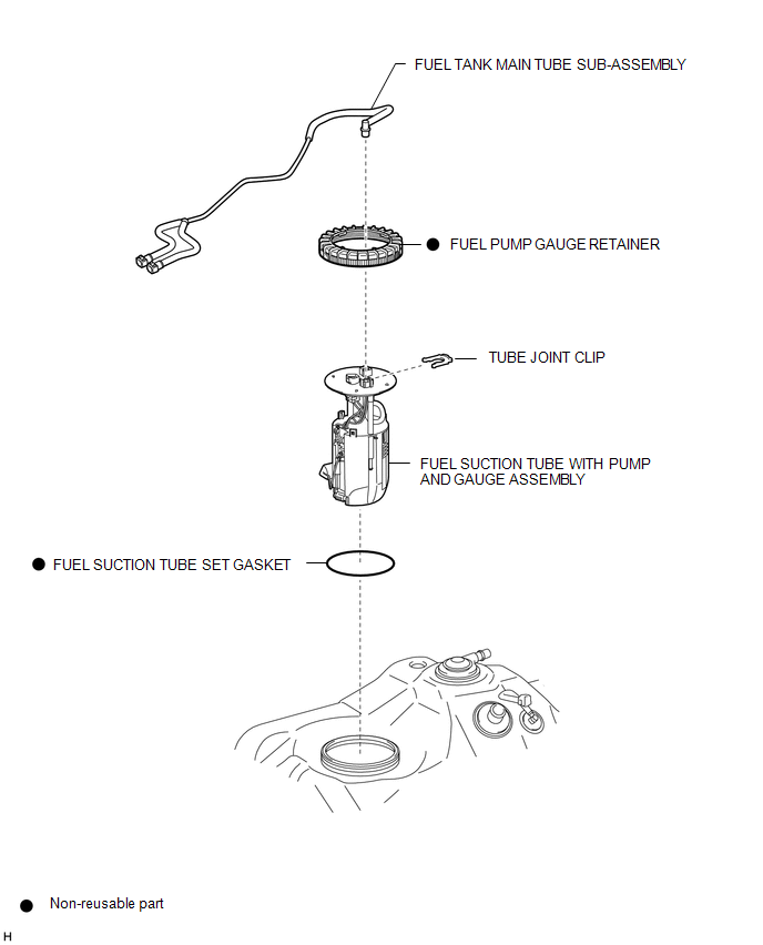
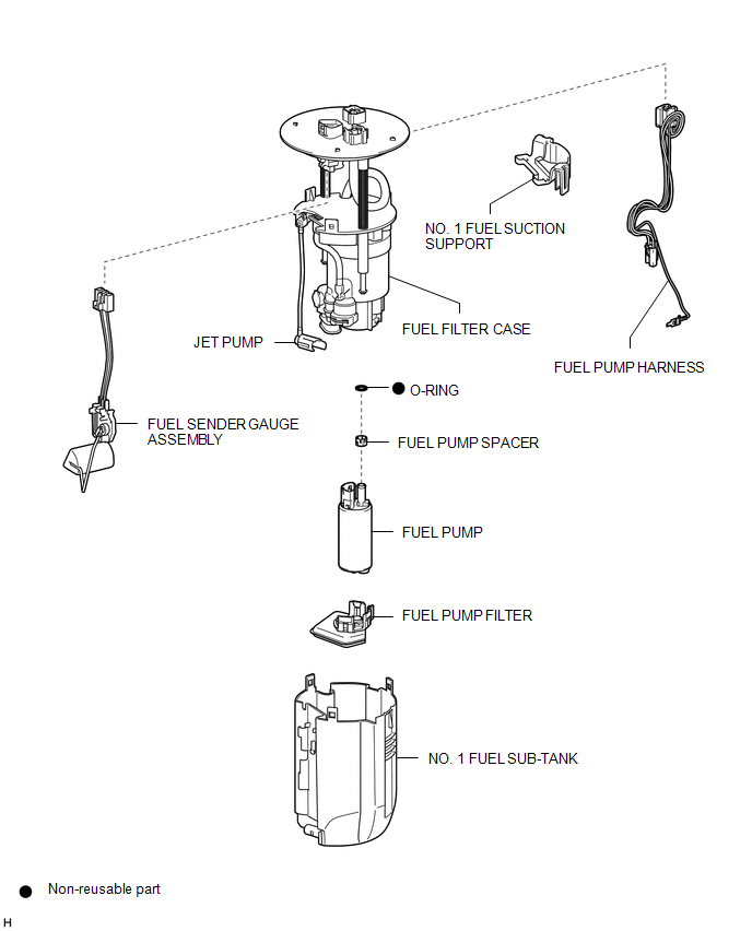
COMPONENTS
ILLUSTRATION
ILLUSTRATION
 Fuel Pump
...
 Disassembly
DISASSEMBLY
CAUTION / NOTICE / HINT
NOTICE:
Do not try to remove the black nylon tube as it is welded to the fuel suction
tube assembly (See page
).
PROCEDURE
1. REMOVE FUEL SENDER GAUGE ASS ...
Other materials:
Reassembly
REASSEMBLY
PROCEDURE
1. INSTALL UN-LOCK WARNING SWITCH ASSEMBLY (w/o Smart Key System)
(a) Engage the 2 claws to install the un-lock warning switch assembly to the
upper steering column bracket assembly.
2. INSTALL IGNITION SWITCH LOCK CYLINDER ASSEMBLY (w/o Smart Key System)
(a) T ...
Problem Symptoms Table
PROBLEM SYMPTOMS TABLE
HINT:
Use the table below to help determine the cause of problem symptoms.
If multiple suspected areas are listed, the potential causes of the symptoms
are listed in order of probability in the "Suspected Area" column of the
table. Check each sy ...
Installation
INSTALLATION
PROCEDURE
1. INSTALL FRONT DRIVE SHAFT
(a) Coat the spline of the inboard joint shaft with gear oil.
(b) Align the shaft splines and install the front drive shaft with a brass bar
and hammer.
NOTICE:
Set the snap ring with the opening side facing downward.
Be caref ...
