Toyota Tacoma (2015-2018) Service Manual: Components
COMPONENTS
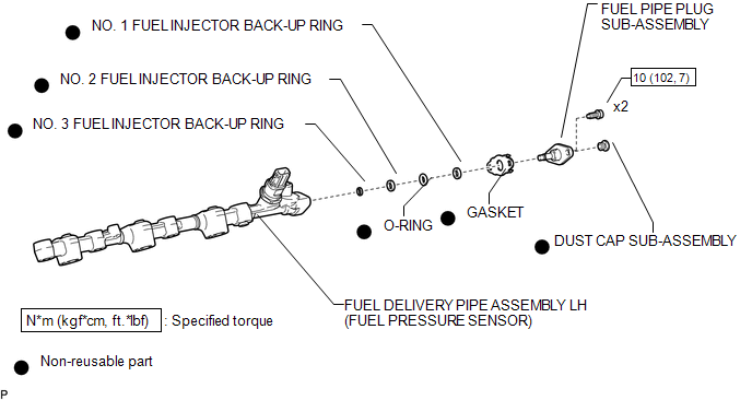
ILLUSTRATION

 Removal
REMOVAL
PROCEDURE
1. REMOVE FUEL DELIVERY PIPE ASSEMBLY LH (FUEL PRESSURE SENSOR)
(See page )
NOTICE:
Do not remove the fuel pressure sensor from the fuel delivery pipe sub-assembly
...
Other materials:
Unable to Unlock Steering Wheel (Engine cannot Start)
DESCRIPTION
The steering lock actuator assembly activates the steering lock motor and moves
the lock bar into the steering column to lock the steering.
The steering may not unlock when the lock bar gets stuck in the lock hole of
the steering column. In this case, if the engine switch is turned ...
VSC OFF Switch Circuit
DESCRIPTION
The skid control ECU assembly is connected to the combination meter assembly
via CAN communication.
Pressing the VSC OFF switch turns off TRAC operation, and pressing and holding
this switch turns off TRAC and VSC operation.
If TRAC and VSC operations are turned off, the TRAC OFF ...
Data List / Active Test
DATA LIST / ACTIVE TEST
1. DATA LIST
HINT:
Using the Techstream to read the Data List allows the values or states of switches,
sensors, actuators and other items to be read without removing any parts. This non-intrusive
inspection can be very useful because intermittent conditions or signals ...
