Toyota Tacoma (2015-2018) Service Manual: Components
COMPONENTS
ILLUSTRATION
ILLUSTRATION
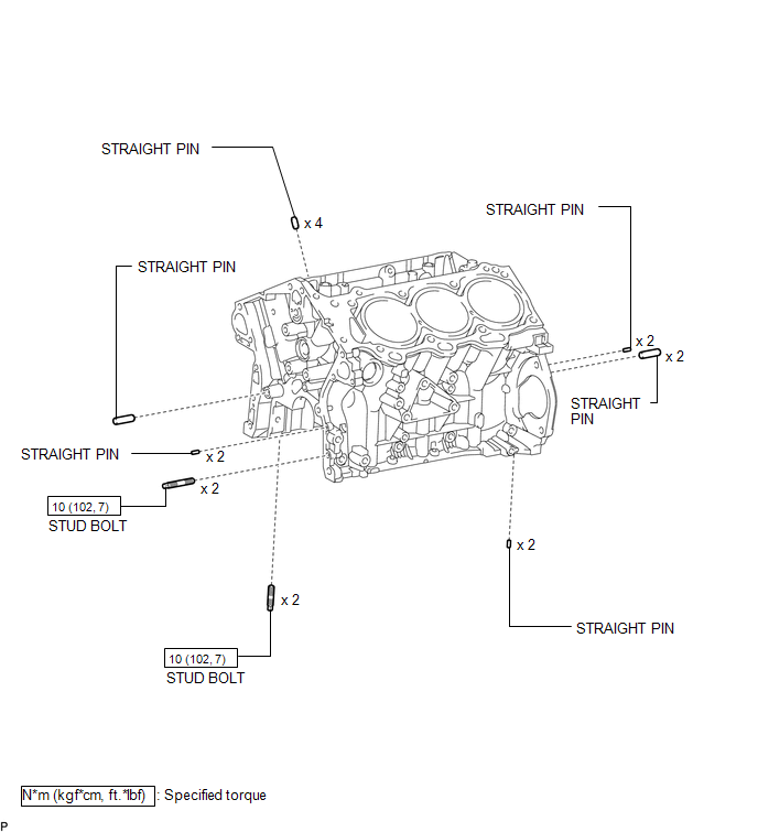
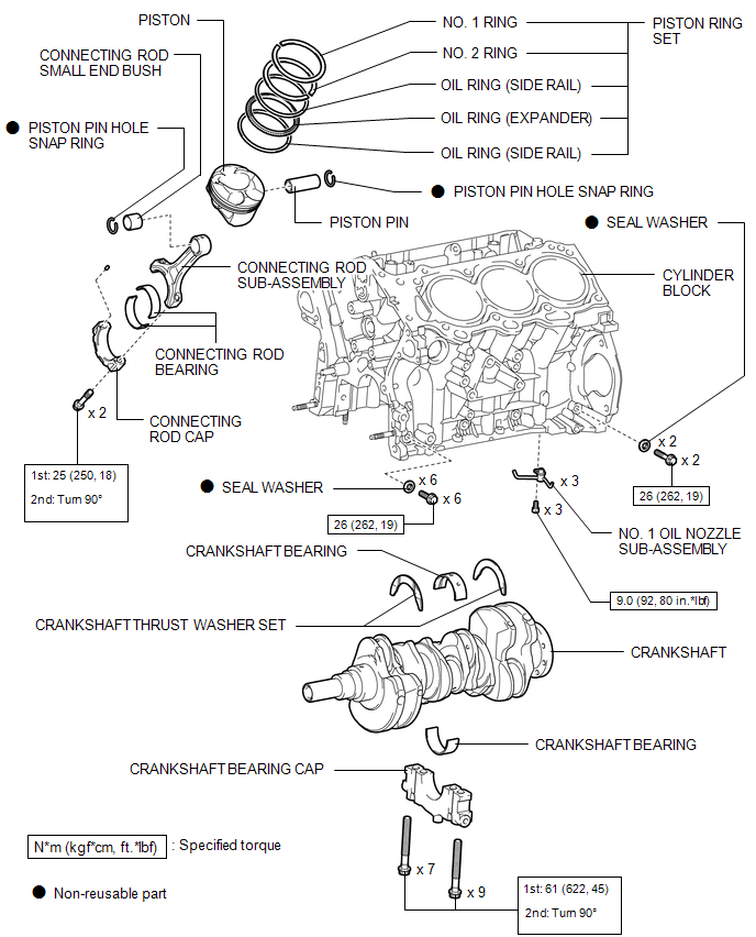
 Cylinder Block
...
 Precaution
PRECAUTION
HINT:
Any digits beyond the 0.01 mm (1/1000 in.) place for standard, minimum
and maximum values should be used as a reference only.
When both standard and maximum or minim ...
Other materials:
Floor mat
Use only floor mats designed specifically for vehicles of the same model and
model year as your vehicle. Fix them securely in place onto the carpet.
Insert the retaining hooks (clips) into the floor mat eyelets.
Turn the upper knob of each retaining hook (clip) to secure the floor mats in
...
Inverter Relay
On-vehicle Inspection
ON-VEHICLE INSPECTION
PROCEDURE
1. INSPECT INVERTER RELAY
(a) Check the resistance.
(1) Measure the resistance according to the value(s) in the table below.
Standard Resistance:
Tester Connection
Condition
...
Auto Up Operation does not Fully Close Power Window (Jam Protection Function
is Activated)
DESCRIPTION
If a door glass or a power window regulator motor assembly does not operate smoothly,
the jam protection function may be triggered automatically, resulting in the auto
up function being unable to fully close the window.
HINT:
This symptom may occur for any of the windows.
CAUTION ...
