Toyota Tacoma (2015-2018) Service Manual: Components
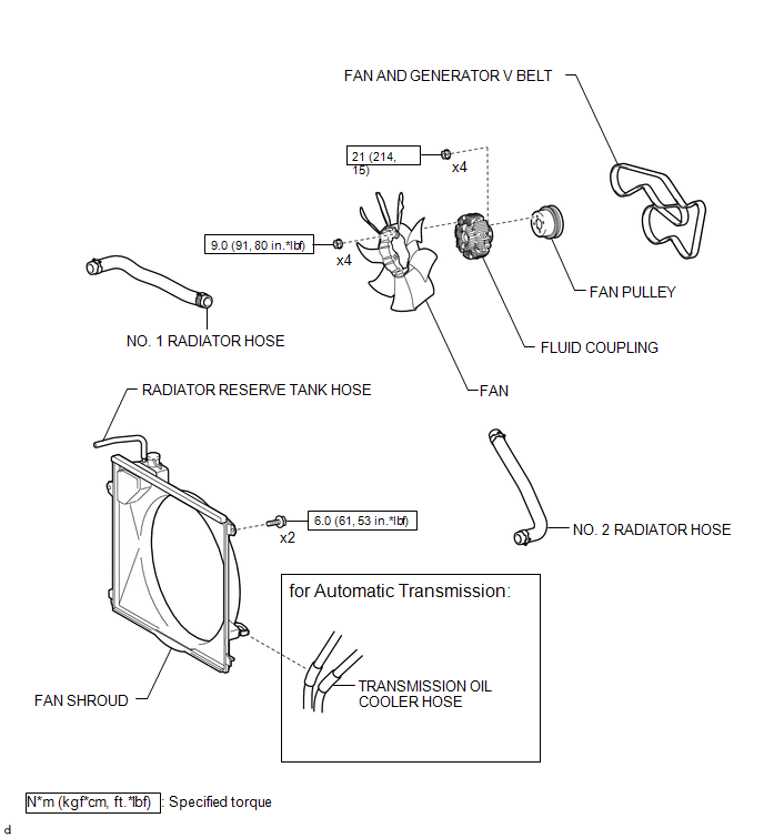
COMPONENTS
ILLUSTRATION
ILLUSTRATION
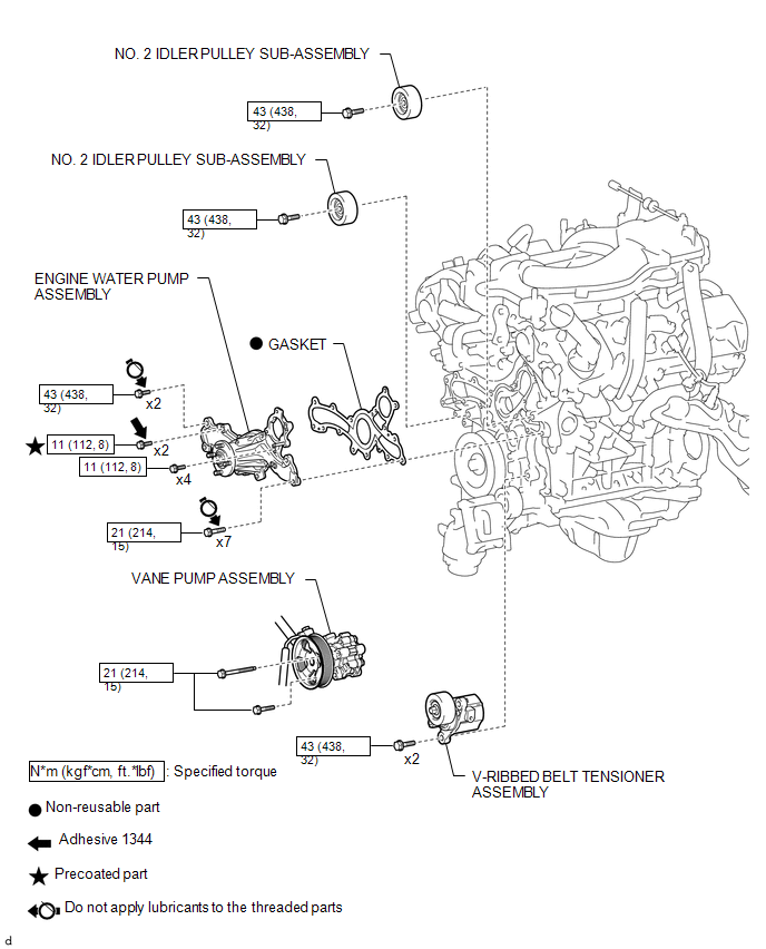
 Water Pump
...
 On-vehicle Inspection
ON-VEHICLE INSPECTION
PROCEDURE
1. INSPECT FOR COOLANT LEAK
HINT:
The sliding surface inside the engine water pump assembly is lubricated
by engine coolant. As some engine coolant is d ...
Other materials:
System Diagram
SYSTEM DIAGRAM
Communication Table
Sender
Receiver
Signal
Line
Millimeter Wave Radar Sensor Assembly
Forward Recognition Camera
Pre-collision alarm signal
Pre-collision braking operation signal
...
Parts Location
PARTS LOCATION
ILLUSTRATION
*A
for Hydraulic Brake Booster
*B
for Vacuum Brake Booster
*1
FORWARD RECOGNITION CAMERA
*2
MILLIMETER WAVE RADAR SENSOR ASSEMBLY
*3
HYDRAULIC BRA ...
Reassembly
REASSEMBLY
PROCEDURE
1. INSTALL REAR BUMPER SIDE STAY LH
(a) Install the rear bumper side stay LH with the 2 bolts.
Torque:
30 N·m {306 kgf·cm, 22 ft·lbf}
2. INSTALL REAR BUMPER SIDE STAY RH
HINT:
Use the same procedure as for ...
