Toyota Tacoma (2015-2018) Service Manual: Components
COMPONENTS
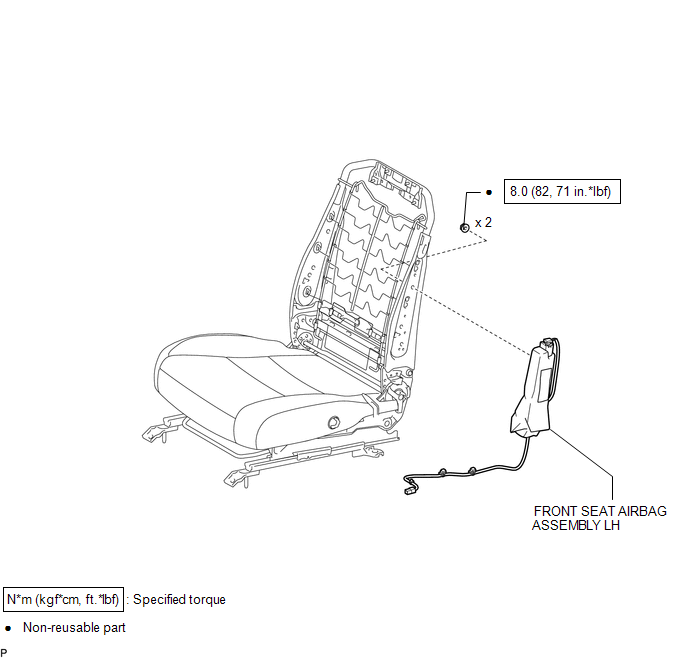
ILLUSTRATION

 Installation
INSTALLATION
CAUTION / NOTICE / HINT
CAUTION:
Wear protective gloves. Sharp areas on the parts may injure your hands.
HINT:
Use the same procedure for both the RH and LH sides.
The pr ...
Other materials:
Problem Symptoms Table
PROBLEM SYMPTOMS TABLE
HINT:
Use the table below to help determine the cause of problem symptoms.
If multiple suspected areas are listed, the potential causes of the symptoms
are listed in order of probability in the "Suspected Area" column of the
table. Check each sy ...
VSC Buzzer Circuit
DESCRIPTION
The skid control ECU (master cylinder solenoid) is connected to the combination
meter via CAN communication.
The combination meter has a built-in VSC warning buzzer:
Sounds intermittently to inform the driver if the temperature of hydraulic
brake booster has increased exc ...
System Description
SYSTEM DESCRIPTION
1. POWER WINDOW CONTROL SYSTEM DESCRIPTION
(a) The power window control system controls the power window operation using
the power window regulator motors. The main controls of this system are the power
window regulator master switch assembly (mounted on the driver door), po ...
